| [ Team LiB ] |
|
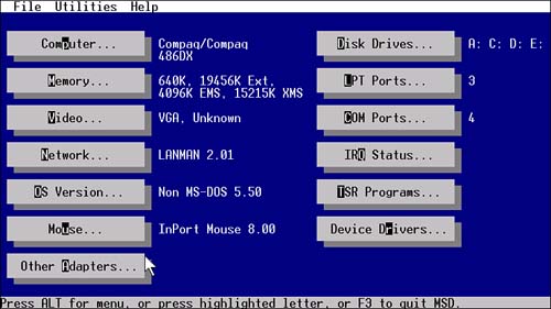
Storage FunctionsBecause the BIOS comes in the physical form of ROM chips, its storage functions should not be surprising. For example, the BIOS stores its own name and the date it was written inside its own code. But the BIOS also incorporates storage functions that go beyond the bytes encapsulated in its ROM silicon. Although physically separate from the BIOS chips themselves, the setup memory of your computer is controlled by BIOS functions and is often considered withand even as part ofthe BIOS. This memory records vital details about your computer hardware so that you don't have to set up each expansion board and disk drive every time you switch on your computer. In addition, the BIOS tells your computer to reserve several small blocks of memory for dynamic data that your computer and its operating system use for tracking several system functions. Legacy DataAs with any computer program, the BIOS code uses data for its operations and produces data as its result. The BIOS stores some of this data to be used as a reference by your programs. The BIOS acquires some of this information as it sets up the system. By storing it all in one place, the BIOS eliminates the need for every program to waste its time looking up common features. Other data is encoded as part of the BIOS itself so that programs can determine what kind of computerand what kind of BIOSthey have to work with. BIOS Data AreaDuring the initialization process, the BIOS searches through the system for specific features. It checks the number and kinds of ports installed, the type of display adapter (monochrome or color), and other options. Included among the data that it stores are equipment flags, the base addresses of input/output adapters, keyboard characters, and operating modes. The BIOS then stores this information in specific memory locations so that your programs can check to see which features are available or being used. For example, the BIOS looks for serial ports at specific addresses (see Chapter 11, "Ports"). As it finds them, the BIOS records the base address that each serial port uses. All this self-descriptive information about your system is stored in a special part of RAM called the BIOS data area. Located just above the interrupt vectors, the BIOS data area comprises 256 bytes of memory, starting at absolute memory location 000400(hex) and running to 0004FF(hex). DateNearly every BIOS identifies itself with a copyright message and (usually) a version number so that you can determine who made it. (More specifically, the copyright message protects the writers of the BIOS from other people copying their work.) This identification information may appear anywhere within the BIOS code range. In addition, the revision date of your BIOS helps you identify how recently its code was updated. As computers have expanded their capabilities, BIOSs have been revised to enable new operations. Sometimes older BIOSs will not work with new peripherals. For example, many BIOSs from before 1998 don't let you use all the space on hard disks larger than 8GB. Older BIOSs may impose even more severe limits. You can determine the date of your BIOS in several ways. The most convenient include catching the bootup screen of your computer, which usually displays the date and revision number of the BIOS, and using a diagnostic utility. Microsoft Diagnostics, supplied with most versions of Windows, will show you the detail of your computer's BIOSits date and manufacturer. This program is located in the Command subfolder of your Windows folder as MSD.EXE. You can either click its icon or run it from the MS-DOS prompt by typing MSD and then pressing Enter. Click the Computer button, and it will list some of the BIOS details of your computer, as shown in Figure 7.2. Figure 7.2. Microsoft Diagnostics showing system details.
Note that Microsoft has not updated the diagnostic program for years, so the most recent microprocessor it will recognize is a 486DX! The System Information program found under System Tools in Accessories from the Programs option at the Start button is Microsoft's preferred tool. It shows your system in exquisite, even painful, detail, but it offers no direct display of your system's BIOS date. System Identification BytesThe original computer BIOS included a byte of data to identify the kind of computer in which the BIOS was installed. Programs that might react differently depending on the processor or other aspects of the computer could use this byte to identify the hardware and adjust themselves accordingly. At least that was the idea of the IBM engineers who came up with it in 1981. The scheme had its problems, however. Allowing for a single byte soon seemed shortsighted, so this memory area was expanded to two bytes, starting with the IBM XT Model 286, introduced in 1985. The overall storage area was termed the system identification bytes, and in IBM nomenclature, it was divided into the model byte and the submodel byte. A third byte was reserved to indicate any major revision to the system. IBM created an elaborate table of designations for the various computer models it offered. Unfortunately, the company made no provision to coordinate the use of this storage area for other manufacturers. Consequently, the rest of the industry used designations marking their IBM equivalent. Because all systems since 1984 follow the architecture of the IBM AT system, nearly all computers now define themselves as using the AT code. In other words, the system identification bytes store essentially meaningless data. The model byte is located at absolute memory address 0FFFFE(hex) and is FC(hex) in nearly all current computers. The submodel byte follows it with a value of 01(hex). The revision byte follows next and is usually zero. The BIOS also has its own individual identification encoded into its bytes. Although it may be nothing more than a copyright notice, each BIOS has some code identifying its origins. Most BIOS makes have their own codes to identify the version of the BIOS, which revision it is, and even the model of computer for which it is meant. Disk Parameter TablesOne of the more important entries in the BIOS data area is the disk parameter table. Most computers store the parameters used by user-defined hard disks, typically reflected as hard disk type 47 in the setup program, in the BIOS data area. The most common memory location for this information is absolute address 0000:0300. Some BIOSs give you the option of locating the disk parameter table in an alternate location, typically DOS memory. In any case, interrupt vector 41(hex) points to the location of the disk parameter table for the first hard disk in a computer. Interrupt vector 46(hex) points to the location of the parameters of the second hard disk. In general, the best location for your disk parameter table is absolute address 0000:0300. However, some peripherals, such as older sound cards and network adapters, use this address for their own purposes. Conflicts between the peripheral and your hard disk may render either or both inoperable. Relocating the disk parameter table through a BIOS setting solves the problem. You may encounter two kinds of disk parameter tables. A standard fixed disk parameter table (FDPT) contains a single description of the vital parameters of the associated hard disk, listing the number of cylinders, heads, and sectors used by the disk. An enhanced fixed disk parameter table (EDPT) has two entries: the logical cylinder-head-sector values and the physical cylinder-head-sector values. The logical values reflect the way your computer sees and accesses the disk. The physical values reflect the actual number of cylinders, heads, and sectors used by the disk. The standard FDPT is sufficient only for smaller disks, those with both fewer than 1024 cylinders and a capacity less than 504MB. Due to the design of the standard FDPT, only ten bits are allowed for storing the number of cylinders, so numbers larger than 1024 cannot be encoded. The EDPT defaults to 16 heads for all disks, allowing four more bits for storing the number of cylinders. Your computer deals with any disk by the logical values in the EDPT. Programmers check the value stored here using software interrupt 13(hex). DOS TablesDOS stores many of the parameters it uses for managing your computer and its programs in a series of tables. To achieve the utmost in compatibility, DOS locates these tables at the lowest available reaches of conventional memory. Among the data stored here are file handle identifications (FILES), the last referenced disk data (BUFFERS), file control information (FCBS), drive tables (LASTDRIVE), and system operating information (STACK). Most memory managers allow you to relocate this data into XMS memory to free up more space in the conventional area. Although this technique is commonplace and well tested, you will sometimes encounter compatibility problems, such as a crash of your system. For example, early incarnations of most network operating systems expect to find this data in conventional memory (along with COMMAND.COM itself). The only way to avoid this problem is to avoid the network, avoid DOS, or refrain from relocating this data with your memory managerthe last usually being the most viable option. You'll want to avoid relocating any of these DOS tables if your system exhibits compatibility problems or its network redirector behaves oddly. ACPI TablesOne of the chief responsibilities of an ACPI-compliant BIOS is to set up the ACPI tables that describe the interfaces to the hardware installed in the system. The operating system can then read the tables to determine not only the resources required by a specific board but also the code with initialization routines or arbitrary operation sequences needed to make the hardware function. The ACPI tables may contain not only data but also program code in p-code, the programming code or the language of the ACPI system. The ACPI specification describes a programming language, called the ACPI Source Language (ASL), in which engineers can write their code for their device interfaces. ASL is then compiled into ACPI Machine Language (AML), the object code that is actually stored in the ACPI tables. The ACPI-compatible operating system reads the AML as a set of program instructions. The BIOS sets up the tables during the boot process. It reads the data for each table from the devices it scans and then stores each table separately in system memory. It makes one master table, called the root system description table, which holds the location of each of the separate data tables. The BIOS itself does nothing with the data it puts in these tables. It is only an agent that moves the data from device to memory. The ACPI-compliant operating system uses the data or p-code contained in the tables. To enable the operating system to find the root system description table, the BIOS plants a pointer in the Extended BIOS data area of memory. The operating system identifies this root system description pointer by looking for the character sequence "RSD PTR" (including the trailing space) in the Extended BIOS data area. The pointer stores the base address of the root system description table from which the operating system can find the rest of the tables. System ConfigurationIn order to properly test a computer, the BIOS needs to know exactly what it is testingwhat peripherals are installed, how much memory it must look through, and whether you have installed a coprocessor. In order to boot a computer, the BIOS needs to know exactly what kind of disk is connected to it. In order for you to see what is going on when your system boots up, the BIOS needs to know what kind of display system you have. In some cases, the BIOS code itself can be written to search out and find the vital information it needs to get your system going. Such a search is not always accurate, nor is it easy to write the proper search method into a few kilobytes of BIOS code. Even if the proper program could be written and packed into ROM, you probably do not want to sit around and waitand waitwhile the BIOS probes into every nook and cranny to see if something is there. To let the BIOS (and the rest of the computer) know what options are installed in a given system, all computers record vital setup information that can be referenced quickly. The storage system for this datathat is, system setup memoryhas one requirement: It must be nonvolatile. Other than that, the storage format and method are flexible because the BIOS isolates them from the rest of your software. The BIOS looks up this system data and transfers it to the BIOS data area for reference by your programs. This flexibility has given designers freedom to use a number of storage technologies for this setup information. Among the most popular have been physical memory (switches), nonvolatile electronic memory, and magnetic (disk) memory. Since the AT was introduced a decade and a half ago, however, the basic form of this setup memory used by most computers has been the samea few bytes of CMOS memory kept fresh (that is, continuously operating) by battery power. CMOSWhen the world and computers were young, all the differences between computers could be coded by one or two banks of DIP switches. But as the options began to pile up, the switch proved to be more a problem than a panacea. A reasonable number of switches couldn't allow for the number of options possible in a modern computer. Another problem with switches is that they are prone to mechanical problemsboth of their own making and otherwise. Switch contacts naturally go bad, and they can be helped along the path of their own destruction by people who attempt to adjust them with pencils (the graphite that scrapes off the point is conductive and can short out the switches). People often set switches wrong and wonder what is awry. BackgroundIBM developed a better scheme for the AT. Vital system parameters would be stored in a special, small block of battery-backed CMOS memory, a total of 64 bytes, in the form of a special chip, a Motorola MC146818, which also held a real-time clock. The lower 14 of those bytes are used by the real-time clock to hold the current time and an alarm time, leaving 40 bytes for storage of setup information. Locations were assigned for storing information about floppy and hard disks, the presence of a coprocessor, the amount of installed memory, and the type of display system (monochrome or color). Because CMOS memory is volatile, every system has a battery of some kind to keep this memory fresh and the real-time clock running. (See Chapter 31, "Power.") Most computers followed the basic IBM scheme, minimally augmenting it to reflect the increasing capabilities of their systems. Although the MC146818 chip rarely appears in computers anymore, its functions are carried over into new support chips. For example, clock modules from Dallas Semiconductor incorporate all the functions of the Motorola chip, a built-in lithium battery, and more. The only major change in CMOS storage that has been made is the almost universal adoption (under the aegis of Microsoft) of the Plug-and-Play system. Basic Memory AssignmentsThe basic CMOS data remains the same regardless of the manufacturer of the computer, and the various bytes of data are stored in the same rigidly structured format. Table 7.3 summarizes the basic storage assignments that are common across nearly all modern computers.
Although the CMOS that holds this data is conventional memory, it is not in the direct reach of your computer's microprocessor. Unlike normal system memory, this CMOS setup memory was I/O mapped. That is, its contents were accessed through two input/output ports. Port 070(hex) indicates the memory byte you want to access, and port 071(hex) provides the pathway to the indicated byte. Reading or writing a byte of CMOS setup memory requires two steps. First, you write to port 070(hex) with the byte location in the CMOS range you want to read or write. Reading port 071(hex) tells you the value stored at the location you have chosen. Writing to port 071(hex) changes the byte value at the appointed location. The contents of most of the storage locations in this CMOS setup memory are monitored by storing a checksum in bytes 02E and 02F(hex). If the checksum does not agree with the modular total of the monitored bytes, your system reports a CMOS memory error. The diagnostic status byte, 00E(hex), indicates the gross nature of the error and additionally reports whether battery power has failed. If all systems are go, this byte has a zero value; any bit set indicates a specific error (with two bits reserved). Newer computers have elaborated on this CMOS storage scheme, adding more bytes to hold the status of other system features. In function and operation, however, all follow the pattern set by the AT. Resetting CMOSThe chief reason you're advised not to tinker with the advanced settings of your computer's BIOS is that the control they afford allows you to set your computer up so that it does not work. For example, if you err by setting too few wait states for the memory you have installed in your computer, you may encounter a memory error as soon as your computer switches on and checks its BIOS settings. You won't have an opportunity to jump back into setup to fix the problem. You'll be stuck with a dead computer and have no way of bringing it back to life. Well, not quite. Most computer BIOSs have factory defaults that are set conservatively enough that the machine will operate with whatever you've installed. The only trick is to restore the factory defaults. Switch or Jumper ResetMany computers have jumpers or a DIP switch that forces the reset. Check the documentation of your computer or motherboard to see if this option is available to you. Typically you'll find this information using the index of your instruction manual and looking under "factory defaults" or "BIOS defaults." The exact procedure usually takes one of two forms, depending on the design of your computer. The easiest requires only that you move a jumper or slide a DIP switch and then turn your computer back on. The position of the switch or jumper doesn't matter. All that counts is that you move it. The most complicated procedure isn't much more difficult. You move the jumper or slide the switch, wait a few minutes, and then move it back. The delay allows the tiny amount of power that's locked in the CMOS circuitry to drain away. Power DeprivationThe alternate procedure for resetting your CMOS works for nearly every computer and is based on the same power-depravation principle. You only need to deprive your computer's CMOS of its battery power so that the contents of its memory evaporate. Exactly how to deprive your CMOS of its lifeblood electricity depends on the design of your system. If your computer's motherboard uses an external battery, simply unplug it from the motherboard. If your computer uses a replaceable disc-style battery in a matching battery holder, pop the battery out. In either case, allow ten minutes for the residual power in the CMOS to drain away before reconnecting or reinstalling the battery. Some motherboards use permanently installed rechargeable nickel-cadmium batteries instead of replaceable cells. Usually these computers have some provision for electrically disconnecting the battery power from the CMOS (a jumper or switch, as noted in the preceding section). A few computer motherboards make no provision for disconnecting their nickel-cadmium batteries (also known as ni-cads). If you have such a computer and have put your BIOS in a nonfunctional configuration, as a last resort you can sometimes force a reset to the factory defaults by discharging the battery. The battery will recharge the next time you operate your computer. Never short out a nickel-cadmium battery to discharge it. The low resistance of ni-cad cells produces high currents (even with small batteries), sufficient to melt circuit board traces and even set your computer on fire. Instead of shorting out the battery, discharge it through a resistor. A half-watt, 39-ohm resistor will safely discharge a ni-cad cell in about half an hour without danger to you or your computer. Alternately, you can use a six-volt lamp, such as one designed for battery-powered lanterns, as a battery load. The lamp will show you the progress of the discharge, glowing brightly at first and dimming as the battery's charge gets drained away. Connect either the resistor or the lamp directly between the terminals of the battery using clip leads. Advanced SetupAfter you press the right combination of keys to bring up your computer's setup menu, you are usually allowed to jump to Advanced Setup. This extension of Setup allows you to alter vital system operating parameters that are controlled by the motherboard chipset. The Advanced Setup procedure alters additional, often proprietary, storage in CMOS and, sometimes, in other parts of your computer. Typically, Advanced Setup is a second menu (or series of menus) accessed through the initial Setup menu. Altering the options can have a dramatic effect on the performance of your computer. Importune tinkering often can lead to having a machine that will not work. Performance becomes zero. On the other hand, you can sometimes optimize your system to take best advantage of the options you've installed (for example, to coax the best possible performance from the memory system or highest transfer rate from your expansion bus). The range of features controlled by advanced setup varies with both the BIOS and the chipset inside your computer. Most chipsets give you a wide range of options to wade through. However, one of the most popular, Intel's Triton chipset, provides very limited control range. For example, the only way to alter the ISA bus speed is to change jumper or DIP switch settings, and you cannot alter cache timing at all. Some of the options available with different chipsets and BIOSs are detailed in the following subsections. Parity CheckSome systems permit you to switch off memory parity checking, thus disabling error detection. Taking this option prevents your system from halting when memory parity errors are detected. You are well advised to leave parity checking enabled except when attempting to find elusive memory problems. Because this option is meaningful only for computers that have parity-checked memory, it offers you no savings as would a system that used 8-bit SIMMs instead of parity-checked 9-bit SIMMs. Your system is likely to halt when a parity-error occurs in program code, but the crash is less controlled than an error-warning message. Files may be destroyed. If the error occurs within data, you may never know when your information is inaccurate. Memory TestingTesting the prodigious amounts of RAM in a modern computer can take a long time, indeed, adding a minute or more to the cold boot sequence. To minimize the wear and tear on your patience, many BIOSs allow you to defeat the entire memory test sequence or specific portions of it. With the claims of extreme reliability for today's memory systems, you may want to consider switching off your computer's memory test. Commonly you'll find an option called Above 1MB Memory Check that allows you to switch off memory testing beyond the base megabyte in your computer. Selecting this option will cut your bootup time from a few minutes to a few dozen seconds. Checking the base megabyte of memory in your computer usually is not an option because your computer needs error-free real-mode memory for running the setup program. Some systems give you the option of adding an audible click or beep each time a memory block of a megabyte or so is tested. The sound is simply reassurance that your computer is successfully coursing through its lengthy memory test. Some people find this sound obnoxious rather than reassuring, and the Memory Test Click Sound setup option allows them to silence their systems. Numeric Processor TestingThe BIOSs of some older computers offer the option of defeating the numeric processor test. Although you might be tempted to forgo this test to accelerate the boot process, you may be surprised at its effect. Many BIOSs assume that if you tell them not to test the numeric processor, you don't have one. They set a flag that tells your applications you don't have a coprocessor installed, so your software won't use the coprocessor even if one is installedeven as part of your microprocessor. Computers based on the 386 and 486 microprocessors may also give you the option of selecting a Weitek coprocessor. You must select this option to enable your software to take advantage of the Weitek chip. Cache OperationSome systems require that you set the size of secondary (external) memory cache you have installed. You'll want to change this setting only if you install additional SRAM chips to increase the size of your computer's memory cache. Some BIOSs allow you to switch on or off the cache. Some allow the individual control of the internal (primary) cache inside your microprocessor and the external (secondary) cache. The only time you should switch off your system's caches is when you want to pin down software problems or diagnose hardware errors. Wait StatesThis setting controls the number of wait states injected during memory accesses. Typically, you have a choice of zero, one, two, or possibly three wait states. Some systems allow the separate setting of read and write wait states. Choosing fewer wait states makes your computer faster, but choosing too few to accommodate the speed of your system's memory leads to memory errors. Set this value too low and your computer may not boot at all. If you are a die-hard tinkerer and want to explore the potentials of this setting, adjust it downward one step at a time. Then run your computer for a while to check its reliability. Toying with this may also familiarize you with the location of the CMOS reset jumper. Bus ClockMany ISA systems allow you to adjust the clock speed of their expansion buses so that you can eke the most performance from your old expansion boards. Some systems give you a choice of clock speeds in megahertz; others express the speed in terms of the microprocessor clock (for example, CLOCKIN/4 implies one-quarter the microprocessor clock speed8.25MHz with a 33MHz system). Higher speeds (lower divisors) can deliver more performance, but rates above about 12MHz may sacrifice reliability. In VL Bus and PCI systems, the bus clock setting has less effect on overall performance because the devices that need the most bus bandwidth (that is, a faster bus speed) will be connected to the higher-speed local bus. The clock speed of the local bus is not affected by the bus clock setting. ROM ShadowingManufacturers may provide any of a number of options to enable or disable the shadowing of ROM code in fast RAM memory. Some merely allow the simple enable/disable choice. Others allow you to control ROM elements separately. One variety of BIOS lets you individually enable/disable system ROM and expansion ROM. System ROM means the BIOS code on your motherboard; expansion ROM is the code on expansion boards, which typically includes your video card and hard disk host adapter. Another variety of BIOS gives the choice of system, video, or adapter. A fourth BIOS type lets you choose whether to shadow ROM memory by address range, letting you select enabling or disabling by 16K, 32K, or 64K blocks. In general, you should shadow only those memory ranges actually in use by ROM. Shadowing unused ranges wastes memory. Shadowing memory ranges used for buffers by network adapters or ancient expanded memory (EMS) boards may actually degrade system performance or cause compatibility problems. Remember, shadowing only helps the performance of applications that use BIOS code in ROM, which for the most part means only DOS. If you primarily run any version of Windows or OS/2 that makes little use of the BIOS, shadowing yields no performance improvement and may cause compatibility problems. You will probably want to switch off shadowing when using any modern operating system. Experimenting with shadowing can also lead to a system that does not boot. It is best to enable one block or shadowing feature at a time and then run your system to observe the result. Concurrent RefreshMost early computers must devote 10 percent or more of their active time to refreshing memory. Newer systems are able to refresh memory concurrently (that is, while they are performing normal tasks). Concurrent refreshing ekes more performance from your system, so it is the preferred operating mode. Some BIOS-makers call this kind of memory refresh hidden refresh. Normally your computer will deliver better performance with concurrent refresh. Some older RAM designs (used mostly in 386 and older computers) cannot handle concurrent refreshing and may cause memory errors when this feature is enabled. Page InterleaveSome systems with two or four identical banks of RAM chips or memory modules can operate in an interleaved fashion (that is, alternating banks in back-to-back memory requests). Statistically, interleaving can cut wait states by nearly half. Although the effect is less pronounced in modern cached systems, enabling page interleave (when supported with sufficient memory) can improve performance. Page ModePage mode memory chips and modules also can trim wait states. Page mode SIMMs can make repeated accesses to one memory page without wait states. If you equip your system with page mode memory and enable this option, you should get better performance. Virus ProtectionWith all the concern in the industry about computer viruses, some BIOS-makers have added their own form of protection, a warning message that appears when software attempts to write to the boot sector of your hard disk. When the protection is switched on, you're given the option of canceling the write operation to prevent infection. Because some operating systems, such as the OS/2 Boot Manager, rewrite boot sector data when you switch between boot modes, you can't simply obstruct all boot sector write operations. The protection afforded by this system is limited in two ways. It potentially stops only boot sector viruses. It does not stop those that afflict the active operating system files. Also, it protects only hard disks controlled through the computer BIOS. SCSI disks that rely on separate BIOS code in your SCSI host adapter are not protected. Typematic RateMany BIOSs allow you to alter the way the keyboard reacts to your keystrokes, repeating them if you hold a key down. This feature, called typematic, is fully discussed in Chapter 20, "Keyboards." Many BIOSs have an overall toggle, typically termed Typematic Programming, that enables or disables the settings for the typematic feature. You must enable typematic programming to alter other typematic settings. In addition, your keyboard must allow its typematic feature to be programmed. You can control the typematic feature through Windows 95 and 98 no matter what kind of keyboard you have or the BIOS typematic settings. If a BIOS and keyboard support typematic programming, you can generally alter two aspects of this feature. Typematic Rate Delay specifies how long you must hold down a key before the typematic feature kicks in and characters start repeating. This setting is generally specified in milliseconds. Typematic Rate controls how quickly the characters repeat after the initial delay. This value is usually specified as a number of characters per second that will appear on your screen and in your text. Num LockSome BIOSs let you configure the toggle state of some keyboard keys. The most common option is the setting of the Num Lock key. Most systems default to booting up with Num Lock switched off. This option lets you have your system boot with Num Lock on so you can go right to work crunching numbers. This option is an aid primarily for systems with old 84-key keyboards that lack a separate cursor pad. MS-DOS 6.0 and later enable you to accomplish the same effect as this option by adding the line NUMLOCK=ON to your CONFIG.SYS file. Boot Device or SequenceBy design, computers normally try to boot from the floppy disk first, and only if they find no disk in the floppy drive do they attempt to boot from the hard disk. This strategy helps you get going when something happens to your hard disk so that it's no longer bootable. On the downside, it slows the boot process and forces you to wait for the buzz of the first floppy drive access. It also requires you keep disks out of your floppy drive until after your computer boots up. Although neither of these shortcomings is fatal, they can be bothersome. Consequently, some BIOS-makers give you the option of setting the order that the BIOS searches for a bootable disk drive. Depending on the computer and BIOS-maker, several options are possible. Some BIOS-makers enable you to directly specify the boot order of your computer's disk drives. Typically your options will be listed as "A:, C:" or "C:, A:." Sometimes only the first drive letter will be listed. Specify A: to make your system attempt first to boot from floppy or C: to skip the floppy and try your hard disk first. Other BIOSs have the option Floppy Seek at Bootup, which lets you toggle between Yes or No. If you select No, the BIOS will ignore the floppy disk drive when attempting to boot your computer, even if it has a valid system disk in it. You can take advantage of this option to prevent inexperienced users from booting your computer from their own, possibly virus-infected, floppy disks. Recent systems also give you the option Auto Boot Sequence, or Smart Boot. This is an attempt at the best of both worlds. Most of the time the intelligence of this technique is limited to sampling the floppy disk drive to determine whether it contains a disk, booting from it if the disk is a system disk, and ignoring the drive and booting from hard disk if the disk in the floppy drive is not a system disk or no disk is there at all. PasswordsMany BIOSs have built-in password protection so that you can limit who uses your computer. The setup program typically gives you the option to enable or disable password protection. When you enable protection, the system stores your password in its CMOS memory. If the battery that backs up your CMOS gets low, you'll lose password protection until you replace the battery. Tuning for PerformanceExtra speed is hidden in each of the major components of your computerthe microprocessor, the memory, and your chipset. It takes the form of component tolerances and safety factors, a little bit more than the ratings that every electronic part is good for. By pushing a little harder, you can gain more power from your computer. Although you won't double your system's overall speed, you could gain several percent, enough to give you an edge in game-playing or quicken your daily grind. Fine-tuning your BIOS is the key to unlocking the extra speed potential of your computer. A suitable BIOS will allow you to tweak the configuration of your motherboard chipset and alter microprocessor and memory timing. Each adjustment promises an extra dollop of speed. Unfortunately, the tenability of BIOSs varies widely. Large computer companiesCompaq, Dell, Hewlett-Packard, IBM, Sony, and Toshibagive you control only over a handful of setup parameters that enable you to customize security, add a few peripherals, and configure ports. They don't let you try to eke more performance from your computer because, well, they figure you're likely to screw up. Set the wrong value for a vital parameter, and your computer will stop working and the manufacturer will get a support calland may have to send out a technician to get your machine running again. By not giving you such intimate control, the manufacturer saves on support. Smaller computer-makerssay, the one operating in the garage next doorget a competitive edge by using motherboards with tunable BIOSs. They can tweak in more performance than the bigger computer-makers and give you a faster system. Most makers of motherboards not affiliated with one of the big computer companies have learned that they gain a competitive edge with power users by giving them complete setup flexibility. The pioneer among these companies was Abit, which developed its extremely tweakable SoftBIOS in 1994. Through it and its successors, you can adjust nearly every controllable parameter of your motherboard's chipset. Not only can you adjust the clock speed of the microprocessor to edge up performance by overclocking, you can shave cycles off the inevitable waits for memory refresh and access. With some systems, you can even adjust the voltage supplied to the microprocessor, monitor the environment inside your computer, and set limits on its operation. Most computer-makersand the major brands in particularare conservative in the demands they make on computer components, such as the microprocessor and memory. They prefer to err on the cautious side because it minimizes the need for support. Moreover, they make no allowances for the differences between individual components. You may be lucky and get memory that's rated at 133MHz but will function fine at 150MHz. No motherboard-maker wants to take on the burden of testing the limits of each component when preparing a product. But you can do the testing yourself and set your computer to take advantage of the full potential of its major components. Realistically speaking, the major manufacturers' caution is justifiable. The gains from fine-tuning your BIOS setup are modest, typically a few percentage points. If you're the slightest bit greedy and push your chipset too hard, you can render your computer completely unusable and even destroy the data stored on your hard disk. Go too far, and you can even kiss off an investment in $1000 silicon when your microprocessor melts down into worthless sand. Play it safe. Backup anything that's important on your system before you begin. Familiarize yourself with your motherboard and locate its CMOS reset (if it has one). Also, check for jumper or switch settings for the basic microprocessor and bus operating parameters. Some BIOSs, although they allege to give you complete control through the setup, actually require hardware settings of some vital parameters. Your BIOS may or may not be able to override these hardware settings. If in the process of trying to set the chip speed through your BIOS your system does not cooperate, double-check your motherboard manual for hardware adjustments. Clock SpeedsThe obvious way to eke more speed from a system is to up the microprocessor speed, an enhancement usually termed overclocking because it requires operating the chip over and beyond the clock speed rating set by its manufacturer. Kick up the microprocessor's clock, and you can expect a corresponding linear increase in performance. Raising memory speed also influences the overall performance of your system. The effect can be dramatic because memory performance has not kept in step with microprocessor speed. All modern computer memory systems operate at a fraction of microprocessor speed, requiring the microprocessor to slow down or wait for memory access. On-chip memory caching reduces, but does not eliminate, the waiting. Optimizing the performance of your computer requires considering both the speed at which you operate the microprocessor and the speed at which you operate memory. Not only do you need to consider adjusting both, but in most systems you will also be forced to adjust both. The two speeds interact, and their control is often linked. Most BIOS setup systems do not give you the option of simply changing the microprocessor clock speed because of the design of the chips themselves. Most microprocessors accept a single external clock frequency, which controls the operation of the front side bus or memory bus. The microprocessor speed is derived from this value through a multiplier. Consequently, if you do not vary the multiplier, microprocessor and memory speed settings interact. Up the memory speed and you'll raise the microprocessor speed. The multiplier guarantees that the jump in microprocessor speed will be substantially higher than the memory speed increase (it multiplies the effectwhat did you expect?), and you may soon run past the microprocessor's inherent speed limit. Depending on the actual memory modules installed in your computer, your system's memory system may be more or less tolerant of speed adjustments, as is your microprocessor, even after allowing for the effect of the multiplier. Consequently, you may need to adjust both the clock speed setting and multiplier setting to achieve optimum performance from your system. A further clocking issue is that the design of some motherboards links the PCI expansion bus clock to the front side bus (memory) clock. Although the PCI bus is designed to allow asynchronous operation (it need not be linked to memory speed), many systems do forge such a connection. This linkup can be problematic because PCI devices can be the most speed sensitive in your system. Typical expansion boardsmodems, network interface cards (NICs), and SCSI disk controllersoften develop problems when you raise the PCI bus from its nominal 33MHz speed past about 37MHz. Cycle ShavingIn addition to adjusting the clock speed of memory, many BIOSs allow you to adjust intimate aspects of memory timing (for example, the number of clock cycles required for the operation of the memory system). Most of the available settings control the number of cycles of delay between memory control signals. The opportunities for fine-tuning are amazingyou could spend weeks testing the potential combinations of adjustments. Such attempts will likely be fraught with problems, however. Most adjustments will yield nonworking systems. Moreover, many of them interact, and most make no discernable difference in system performance. The most worthwhile memory parameter to experiment with is the Column Address Strobe latency, or CAS latency. This setting adjusts the number of clock cycles the system waits in between reading bits in the same memory column. A lower value means less waiting and thus a faster computer. Typical CAS latency values in Pentium III-class and Athlon systems range from two to four cycles. Some BIOSs may even allow half-cycle values (for example, 2.5 cycles). From a technical standpoint, adjusting CAS latency rather than clock speed holds an advantage of a different type. Changing the CAS latency does not raise the operating speed of any part of the computer. Hence, it should not add to the heat stress of any computer component and should not affect the life of your computer's circuits. System IntegrityPushing any component beyond its rating runs the risk that the component will no longer operate. A single malfunctioning component can lead to your computer no longer booting. But just because your computer boots after you make a BIOS adjustment that affects performance does not mean all is well. You still run the risk that one or more of the parts inside your computer are on the edge of failing. As a result, your computer may boot, but may not operate reliably. Memory errors are among the most likely problems to arise from pushing memory speed up. Although server memory often has built-in error correction to ward against memory problems, most modern workstations, desktops, and notebook computers lack even parity-checking memory that warns of memory errors (by halting the system). These unprotected systems can develop memory errors without warning, and these errors can ripple though your system until it crashes. In other words, adjust memory speed cautiously, and don't depend on a souped-up system until you've given it time to prove itself. Microprocessors, too, become unreliable if operated at speeds that are too high. Some BIOSs, however, allow you to help your microprocessor cope with high clock speeds by increasing the core voltage. Higher voltages allow the chip to operate faster without sacrificing data integrity. If you increase your microprocessor speed significantly, you may want to increase its core voltage to ensure its reliable operation. The corollary also applies. If you increase the core voltage of your microprocessor, you should be able to increase the chip's clock frequency more than would have otherwise been possible. You won't find guidance as to the relationship between voltage and potential speed increases anywhere. Chip-makers test only at design voltages and frequencies. Motherboard-makers defer to the chip-makers, warning only that you should keep within the range specified by the chip-maker. Your only choice is to try and see. Before adjusting microprocessor core voltage, be sure that you have adequate cooling for your chip. Microprocessor power useand therefore heat outputincreases to the square of the increase in voltage. Consequently, a small voltage increase can quickly lead to the overheating of your microprocessor and, potentially, its self-immolation. BIOS-makers provide some help with this issue, however. Among the settings for most BIOSs affording voltage control are temperature sensors that allow you to monitor both chip temperature and the temperature inside your computer's case. Some allow for warning when temperatures exceed the limits you set. You may be able to set a shutdown temperature for your microprocessor. Even these shutdown temperature settings don't guarantee the safety of your expensive silicon, however. The temperature probes measure the microprocessor's external temperature, not the temperature at the semiconductor junctions where damage actually occurs. If you grossly increase the voltage to the microprocessor, the junction temperature can skyrocket into the meltdown range well before any external chip sensor detects a significant temperature change. In other words, step cautiously. If you are tempted to try increasing chip core voltage, do so in small incrementsand carefully monitor chip temperature after each change. Other OptionsSpeeding up clocks and shaving cycles aren't the only ways you can potentially pluck more performance from your system through BIOS adjustments. Many BIOSs afford you some opportunity to optimize the waits inherent in bus access. In addition, nearly all modern BIOSs allow you to shadow the BIOS code itself. Although these adjustments sound promising, in reality they do little to improve the overall speed of your system. For example, the real purpose of the bus recovery time adjustments is to help achieve compatibility with older expansion boards. Both the 8-bit I/O recovery time and 16-bit I/O recovery time settings present in the BIOSs of systems with both PCI and ISA expansion buses let you slow down the system to accommodate marginal expansion boards connected through the legacy or ISA bus. Although increasing the recovery time, usually measured in bus cycles, may allow you to use older ISA expansion boards, decreasing it will not affect normal system performance. BIOS shadowing copies the BIOS firmware from ROM to RAM. In theory, it enables your system to read the BIOS code from RAM (32-bit or 64-bit) memory instead of 8- or 16-bit ROM memory. This should speed up BIOS-mediated operations substantially. However, modern operating systems, including Linux and all varieties of Windows from 95 through XP, sidestep the BIOS by using drivers that take direct control of system hardware. Shadowing will not affect the performance of programs run under any of these modern operating systems. In other words, shadowing is a carryover from the days of DOS that's essentially irrelevant to modern computers. Leaving BIOS shadowing off will help ensure system stability and slightly increase available memory. Video shadowing is similarly ineffectual in accelerating today's software. Windows uses its own drivers that directly access video hardware, so video shadowing does not affect normal system performance. Some BIOSs also offer adjustments for your system's memory cache. Depending on the BIOS, you may have individual control of both Level 1 (L1) and Level 2 (L2) caches, which are sometimes termed primary and secondary, or more confusingly, internal and external (confusing because both the L1 and L2 caches are internal with many microprocessors, such as current Athlon, Duron, Pentium III, and Pentium 4 chips). Your BIOS may also allow you to selectively switch off the microprocessor read cache or write cache. No matter. In any case, the only potential here is for slowing down your system by turning the cache off. These cache controls are not designed to adjust performance. Rather, they are useful only for troubleshooting or preventing problems with software. But programs that have problems with the cache are probably programs you shouldn't be running. Tuning your system with its BIOS is inevitably a trial-and-error experience. You are investing your time to make tests more rigorous than those made by chip manufacturers so that you can run all of your computer's components as close to the edge as possible. |
| [ Team LiB ] |
|