| [ Team LiB ] |
|
SCSI Parallel InterfacePronounced scuzzy by much of the computer industry (and much less often sexy by its most fervent advocates), SCSI is a system-level interface that provides what is essentially a complete expansion bus into which to plug peripherals. SCSI isn't simply a connection that links a device or two to your computer. Rather, it functions like a sub-bus. SCSI devices can exchange data between themselves without the intervention of the host computer's microprocessor. In fact, they can act across the SCSI bus even while other transfers are shifting across the host computer's normal expansion bus. SCSI is even older than ATA. In fact, it's effectively the oldest interface still in use in personal computers. Originally simply a means to add hard disk drives to minicomputers, SCSI has evolved into a complete interconnection system that can link hard disk drives, CD-ROM players, scanners, and even arrays of hard disks to any kind of computer. The basic SCSI hardware interface is a parallel connection on a multiconductor cable called the SCSI Parallel Interface (SPI). In original form, the SCSI interface comprised an eight-bit bus with a ninth parity bit for error detection and a maximum clock speed of 5MHz. Since then, four versions of the SPI system have been developed, the most recent of which (SPI-4) pushes the width of the bus to 16 bits (not counting parity) and the peak data rate to 320MBps. More a place to plug in hard disks, SPI has become an expansion bus that can link up to 15 devices of various types to your computer through a single-port connection. All the devices function independently, under the control of the host system through the host adapter that provides the SCSI port. StandardsThe original SCSI standard evolved from another interface called SASI, the Shugart Associates Standard Interface, developed in 1981 by hard-disk pioneer Shugart Associates working with NCR Corporation. Together they developed SCSI as an eight-bit parallel connection between host computers and disk drives. Later that year, the X3T9 committee of the American National Standards Institute used the SASI specification as the foundation for its work on a parallel interface standard. That standard, now known as SCSI-1, was formally approved in 1986. Even before the ANSI acceptance of SCSI, manufacturers were wary of the shortcomings in the original specification. In 1985 device manufacturers approached the group working on the standard with proposals to increase the mandatory requirements of the SCSI standard. Because the standard was already near completion and the industry was impatient, ANSI adopted SCSI while at the same time forming a new group to develop a set of commands for SCSI with broader application, eventually published (though not as an official standard) as the Common Command Set. Because the Common Command Set was not a mandatory part of SCSI, each device manufacturer made its own interpretation of it. As a result, individual SCSI devices often required their own driver software, and many combinations of SCSI devices simply wouldn't work together at all. SCSI-2In 1991, a revision of SCSI was introduced to help fix some of the problems in mating SCSI devices, as well as to increase the speed of SCSI transfers. Referred to as SCSI-2, the new standard integrated the newly developed Common Command Set with several optional hardware enhancements. Through the Common Command Set, SCSI-2 embraces communications as well as other storage devices. It incorporates specific command sets for read-only and erasable optical devices, in addition to CD-ROM. Other commands control devices that can change the medium on which they store data (for example, cartridges), such as optical jukeboxes. SCSI-2 also includes commands for printers (carried over from the original SCSI), scanners, and communications equipment. Hardware improvements included the broadening of the eight-bit SCSI data bus to Wide SCSI, which doubled the bus width to 16 bits. In addition, the top speed of SCSI transfers was doubled with the addition of Fast SCSI. With an eight-bit bus width, Fast SCSI pushed transfer rates up to 10MBps; Wide and Fast SCSI could peak at 20MBps. Wide SCSI also expanded the number of possible devices connected to a single host adapter channel from 7 to 15. SCSI-3Almost immediately after the SCSI-2 standard was approved, the industry began work on its successor, SCSI-3, to refine the standard further. Although not formally approved at the time this was written, SCSI-3 has been out in draft for long enough that most manufacturers have incorporated its requirements into their designs. For the purposes of this discussion, SCSI-3 is considered the current standard. Rather than a single standard, SCSI-3 has become an umbrella that covers a multitude of individual hardware and protocol standards. Notably, it divorces software from hardware so that the Common Command Set and the various cabling systems go their separate directions. At that, SCSI itself becomes a command protocol, and the various interconnection standards control how you wire your peripherals together. At the hardware level, SCSI-3 brought with it the first generation of the SCSI Parallel Interface, along with three other interconnection systems. Serial Storage Architecture currently delivers two channels of 20MBps transfer rate for full-duplex operation (a device can transmit and receive simultaneously at that data rate). P1394 gives a 100MBps serial system that plugs together like a set of stereo components. Fibre Channel Arbitrated Loop provides a 100MBps system that uses simple plug-in connections for the disk drive and a bridge to optical fiber with even higher speeds. These hardware standards give SCSI-3 enough headroom to take peripheral connections into the next generationand the next incarnation of SCSI. After the introduction of the SCSI-3, the parallel interface was independently revised as SPI 2 through 5 (currently). Table 10.10 summarizes some of the various SCSI standards, their official designations, and the popular names of the speed modes included under them. ClockingSCSI Parallel Interface allows for both asynchronous and synchronous transfers. Asynchronous transfers allow data to be sent at irregular intervals using start and stop bits to mark the beginning and end of data bytes. Synchronous transfers use system timing to define data bytes. Because synchronous transfers require less overheadfewer bits need to be transferred and less processing of the data is requiredthey can be faster. The first implementation of synchronous SCSI is sometimes called Fast SCSI, usually with a designation of the bus clock speed. Asynchronous SCSIAsynchronous SCSI operates as a handshaking system. First, a device issues a request (signaling REQ) and waits for an acknowledgment (ACK) to be sure its request was received before doing anything else. In every step and every byte of the transfer, this two-step process must take place. Actual transfers require four steps: First, one device sends the REQ and it is answered by ACK. The first device turns off its REQ and waits for the other device to switch off its ACK before the first device can go on to the next byte. Each of these handshakes must travel down the SCSI cable, so the signal must go back and forth through the cable twice for each transfer. Although electrical signals are fast, they travel at a finite and measurable speed, about one-third the speed of light in a vacuum. In typical SCSI cables, it takes a signal about 5.25 nanoseconds to move one meter. This travel time is termed the propagation delay, and it is the primary constraint on the speed of asynchronous SCSI transfers in long cables. The longer the cable, the longer the delay. Although the original SCSI standard puts a speed limit of 1.25MBps on asynchronous transfers, that rate applies only to the longest permitted cables, 25 meters. Shorter cables can achieve higher rates using asynchronous transfers. The overhead involved in transferring each byte across the parallel SCSI bus using asynchronous signaling is about 160 nanoseconds. Adding in the propagation delay sets the minimum cycle time and maximum transfer rate of the connection. Synchronous SCSISynchronous SCSI requires an acknowledgment for each request sent, but it allows the acknowledgment to be delayed. Consequently, a device can send packets one after another without enduring the propagation delays required in interlocked handshaking. Synchronous SCSI operates at a speed determined by its cycle time without regard to propagation delay. In other words, the speed of synchronous SCSI is independent of cable length. The first clock speed specified for synchronous transfers was 5MHz. Through the years, the standard has raised this speed, with each improvement doubling the speed of its predecessor. Each improvement also earned a distinctive name. Fast SCSI boosts the clock speed to 10MHz. Ultra SCSI kicks it up another increment to 20MHz. Ultra2 SCSI doubles the speed again to 40MHz. Ultra160 SCSI doubles it again, to 80MHz. Today's fastest, Ultra320 SCSI, leaves the bus speed alone but double-clocks the data so that transfers are made on both the rising and falling edge of each clock cycle. Therefore, data moves at twice the clock speed. The most recent SPI standards also permit double-clocking, the transfer of two data bits on every clock pulseone on the rising edge, one on the falling edge. In fact, double-clocking is necessary to achieve the highest peak rates for all the most recent SPI standards. Double-clocking was introduced with the SPI-3 specification. Bus WidthThe current SCSI parallel interface standards allow the use of either an 8- or 16-bit data bus, with the latter moving data twice as fast as the former. The 16-bit version usually is called Wide SCSI. Under early SCSI standards, a wider, 32-bit bus was also allowed, although it was never commercially implemented. The SPI-3 standard declared the 32-bit bus obsolete. Under the SCSI-3 standard, Wide SCSI is an optional implementation. However, the wide bus is mandatory for Ultra160 and Ultra320 SCSI connections. Table 10.11 lists the nomenclature and speed limits (more correctly, peak transfer rates) of today's common parallel SCSI connection systems. Capacity and AddressingSCSI devices store data in the form of blocks. Each block is assigned an address, and a host indicates which block to read or write by its address. The size of each block and the number of available addresses constrain the capacity of any given device. The original SCSI command structure provided 21 bits for identifying block addresses, sufficient for 2,097,152 blocks. With hard disk drives that used blocks of standard 512-byte sectors, this addressing scheme allowed for drives storing up to 1GB. The SCSI-2 refinement allows for a full three bytes (24 bits) for encoding block addresses by taking advantage of three bits reserved under the earlier implementation. SCSI host adapters designed to that standard can access up to 16,777,216 blocks, which with sector-size blocks limits capacity to 8GB, or 8,589,934,592 bytes. Larger drives could be accommodated by defining blocks as multiple sectors. Increasing block size is a band-aid solution, one that only covers up an underlying problem. Consequently, the current SCSI Block Commands now include a second form of read, write, and related commands that allocate four bytes (32 bits) for block addresses. Using the new commands, the system can address up to 4,294,967,296 blocks, enough to handle devices storing 2TB (2,199,023,255,552 bytes) of data. Note that some early SCSI host adapters suffered addressing limits imposed by design choices made by their manufacturers. In particular, many old host adapters made before about 1995 may limit addressing to 1GB or less. In other words, large-capacity SCSI devices may not work properly with older host adapters. SignalingSCSI systems can use any of three kinds of signaling: single-ended and two forms of differential signaling. Early generations of SCSI devices used single-ended signals, as do many modern low-cost and/or low-speed devices. Differential signaling allows for higher speed and is mandatory under the fastest SPI standards. Single-ended SCSI uses an unbalanced (or single-ended) electrical signala single wire for each signal, with all signals in the bus using a single common ground return. Differential SCSI uses balanced (or differential) signals. Each signal on the SCSI bus has its own return line that is isolated from the reference ground. Differential SCSI signals use twisted-pair wiring. Most SCSI implementations have been single-ended because they require half the pins, cheaper wire, and simpler electronics than do differential SCSI implementations. As with all single-ended electrical systems, single-ended SCSI is more prone to picking up noise and interference than differential SCSI. As a result, the specifications for SCSI systems that use single-ended signals limit cable lengths to no more than 6 meters (just under 20 feet). Differential SCSI allows for bus lengths up to 25 meters (about 82 feet). You must have at least one-third meter (about 12 inches) of cable between SCSI devices, so the shortest possible SCSI cable is that length. External SCSI cables should be shielded. The voltages on the single-ended SCSI vary a bit with speed. The levels used are summarized in Table 10.12.
Instead of centering the logic signals on zero volts, differential SCSI signals are designed so that the currents flowing during logic transitions exactly cancel out each other in the two signal conductors. When one of the two differential signal lines transitions from low to high, the other goes from high to low. Even though both high and low are positive values, the current flows cancel. The current flow generates the magnetic field that limits performance as well as generates interference. The first differential signaling system used by the SCSI system was quite tolerant of high common-mode voltages (for instance, noise). Called High-Voltage Differential (HVD) SCSI, the difference between low and high signals was required to be one volt or more. The maximum voltage for a low signal is 1.7 volts; the minimum for a high signal is 2.7 volts. The common mode voltage, which is the same on both the positive and negative signals lines, can range from 7 to +12 volts. The SPI-3 standard declares HVD signals obsolete. They should no longer be used in new SCSI devices. The SPI-2 specification introduced another differential signaling scheme that ensured the appearance of only lower voltages on the SCSI lines, making the system compatible with single-ended signaling. Called Low-Voltage Differential (LVD) SCSI signaling, this scheme is optional for speeds of 20MHz and under and mandatory for clock speeds of 40MHz and higher, including Ultra2 SCSI, Ultra160 SCSI, and Ultra320 SCSI. WiringBecause SCSI is a bus, its wiring is essentially simple. The pins of the connectors on one device are directly linked to the pins of the same position (and function). You can run a straight cable (no twists or crossovers) from the host adapter to one SCSI device, then on to the next. Unfortunately, reality interferes with this idealized connection system. All the variations of the parallel interface need to be taken into account. As a result, the mechanics of the actual cabling vary with bus speed and width, whether your SCSI connections are strictly inside your computer, external to it, or both. SCSI also saddles you with two other worries: device identification and termination. The proper operation of a SCSI system requires that you get both of these setup chores right. SCSI IdentificationAs a bus, all devices are simultaneously connected and receive all transmissions (commands and data). Commands are routed to individual SCSI devices by identifying them by their SCSI address. Standard SCSI systems use eight dedicated lines in the SCSI cable for identifying devices. Each device uses one line, allowing eight unambiguous addresses that translate into SCSI identification (SCSI ID) numbers. In eight-bit SCSI systems, these are usually designated in standard Arabic numerals as SCSI ID numbers 0 through 7. Wide SCSI systems expand the identification possibilities to 0 through 15. In either case, one number (usually the highest) is reserved for the SCSI host adapter. The other addresses, 0 through 6 or 0 through 14, can be assigned to any device connected anywhere in the SCSI chain. Each address is assigned a priority to the device using it, with the host adapter having the highest address (7 or 15) and therefore the top priority. The device with a SCSI ID of 0 always has the lowest priority. In the latest SCSI systems that operate under the Plug-and-Play aegis, you don't have to worry about these numbers. The SCAM system (which stands for SCSI Configured Automagically) does exactly what its name impliesit queries each SCSI device and assigns nonconflicting ID numbers to each one it finds. For SCAM to work, of course, your host adapter, operating system, and SCSI devices must comply with the standard. Note, by the way, the magically part of the name was applied in the initial standard, although some less inspired engineers are apt to interpret the name to be SCSI Configured Automatically. If you have an older host adapter and a mess of old SCSI devices, you'll be left to configure them without prestidigitation. And that's where the complication of SCSI begins. Except for the arbitrary address of 7 assigned to the host adapter (or 15 in Wide SCSI systems), you assign the addresses that each SCSI device uses. The most basic rule is simple: Each SCSI ID number must be unique, so never assign the same ID number to two or more devices in the same SCSI chain. In the formal SCSI scheme of things, you can assign any number to any device, as long as you configure your software properly. The SCSI specification does not reserve any particular number for any device. As a practical matter, you cannot be so cavalier about the ID numbers that you use for different devices. One concern is matching your software. A SCSI driver may require that you indicate the SCSI address that you assign to your CD-ROM player. The software for the CD-ROM player may demand that you assign a particular address to the player in order for it to work. If there is any one guide to follow, it is the model set by Adaptec, the largest maker of SCSI host adapters. To provide some consistency for its host adapters that emulate Western Digital WD1002 controllers so they can boot your computer, Adaptec chose rather pragmatically that you must assign your boot hard disk drive (if it is a SCSI drive) ID number 0. Newer SCSI systems allow you to choose the ID number for the boot device. The SCSI ID controls the arbitration priority of the device to which it is assigned. In the SCSI scheme, device ID 0, oddly enough, receives the lowest priority in arbitration. Device 7, usually the host adapter, receives the highest priority. In Wide SCSI systems with a 16-bit bus, the priority system is a bit more complex, but device 7 maintains the greatest priority. Table 10.13 summarizes the relationship between device ID and arbitration priority on the Wide SCSI bus.
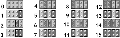
Early host adapters had built-in BIOSs that enabled the boot drive and one additional drive to link to your computer without an additional software driver. In order for your second drive to be recognized when using this kind of controller, the second hard disk must have ID number 1. Many of the latest SCSI host adapters include an advanced BIOS capable of recognizing up to seven hard disk drives, giving you the freedom to assign them any ID, providing you give the boot device ID 0. The BIOS recognizes disk drives (and dispenses drive letters) according to the order of the ID you assign. The lower numbers get the first drive letters. Some host adapters put one more restriction on your freedom in assigning device IDs. If you cannot get a device to be properly recognized in a SCSI system based on an older host adapter, you may need to check the host adapter manual to see if it enforces any restrictions on SCSI ID assignment. Internal SCSI devices such as hard disks typically have several jumpers or switches on each device that set its SCSI ID. The location of these selectors varies, but they're usually easy to find. Look for a set of jumpers with some form of the legend "ID" silk-screened on the circuit board. Older drives often offer a row of seven jumper pairs numbered 0 through 6, with one jumper spanning a single pair. With these, setting the ID is easy. Move the jumper to the ID number you want. Other drive manufactur ers use a binary code to set the ID, so you'll face a set of three header pin pairs that require from zero to three jumpers, depending on the ID you want. Newer drives typically use a binary code for assigning the ID number. Four pairs of pins allow the choice of any ID from 0 to 15. Figure 10.5 gives an example of this binary coding scheme. Figure 10.5. SCSI ID binary code shown as jumper positions.
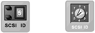
Drives vary in the location and labeling of these identification pins, so you should check with the instructions supplied with a given drive or the drive-maker's Web site for guidance in setting the ID number you want. External SCSI devices commonly use two forms of selector switches for choosing the SCSI ID number assigned to the device: pushbutton and rotary switches. Figure 10.6 illustrates both of these selectors. Figure 10.6. The pushbutton (left) and rotary selector switches for setting the SCSI ID.
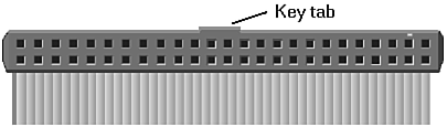
Pushbutton selectors allow you to ratchet up and down the series of identification numbers by pressing two push-tabs on the selector. Some switches cycle around and around without stopping; others limit their movement from 0 to 7. You only need to push the appropriate button until you see the SCSI ID you want in the small adjacent window. Rotary switches select the SCSI ID numbers like an old-fashioned television channel selector, the miniature equivalent of the rotating knob. Most of these rotary switches require a small screwdriver to adjust, preventing them from getting inadvertently changed by bumping the back of the SCSI device. Note that nothing in the design of the SCSI Parallel Interface precludes two computers sharing one chain of SCSI devices except for SCSI identification numbers. Because each device in a single chain must have a unique ID, two host adapters assigned SCSI ID 7 cannot coexist. If you can alter the ID number assigned to the SCSI host adapter in either computer, however, you can connect both in a single SCSI chain. Either computer will be able to access the various devices. In theory, the two computers could transfer files between one another as well, but most SCSI software makes no provision for such installations. Cable ConnectionsOnce you've manually configured your SCSI devices with the proper ID numbers (or left matters to the Fates under SCAM), you have to connect them all together. The SCSI system uses a straightforward daisy-chain wiring systemeach device connects to the next one down the line. The exact mechanics of the wiring system depends on whether you have internal or external SCSI devices or a mixture of both. Internal DevicesAn internal SCSI system is like a flexible expansion bus. Instead of connectors to a printed circuit board, the bus takes the form of a ribbon cable, and the expansion connectors are plugs on the cable. One end of the cable plugs into your SCSI host adapter. Each drive attaches to one of the plugs in the cable. All plugs on the cable have identical signals, so you can use any convenient connector for any SCSI device. The devices and host adapter use SCSI ID numbers to sort out which commands and data go where. For best operation, always plug a device into the last connector at the end of the cable. When this device is terminated (explained later in this chapter), it prevents signal reflections from the end of the wire that might interfere with the operation of the SCSI system. Modern SCSI devices may use 50-, 68-, or 80-pin connectors. The last two (and one form of the first) are molded in a vague "D" shape that acts as a key, so you cannot plug in a drive improperly. Older 50-pin connectors sometimes are not keyed and can pose orientation problems. As with nearly all ribbon cable systems, a red (or sometimes blue) stripe on one edge of the cable used by SCSI devices marks the polarity of the cable. The stripe corresponds to pin 1 of the SCSI connector. Most internal 50-pin SCSI connectors and receptacles are also keyed with a tab and corresponding notch in the middle of one long edge of the connector and receptacle. When you look into the holes of the cable-mounted female SCSI connector with the keying tab on top, pin 1 (and the red stripe) appears on the left, as shown in Figure 10.7. Figure 10.7. The keying of an internal SCSI cable connector.
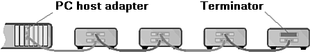
The SCSI cable in systems with 50-pin and 68-pin connectors links both control and data signals. However, it does not provide power to the individual internal SCSI devices. Each SCSI device will also require you to plug in its own power connector. The 80-pin SCA system includes power in its connections. Drives that use the 80-pin system are designed for hot-swapping. You can plug them in at any time, even when your computer is running. The other connection systems require that you switch off your computer before you plug in a drive. External DevicesExternal SCSI cabling is somewhat different from that of internal devices. Using the external SCSI cabling system, you run a cable from the host adapter to the first device in the external SCSI chain. For the next device, you plug another cable into the first device and then plug the other end of the cable into a second device. Just continue in the same manner, adding another cable for each additional device. Most external SCSI devices have two SCSI connectors to facilitate their daisy-chain connection. It doesn't matter which of the two connectors on the SCSI device you use to attach each cable. Functionally, both connectors are the same; each is equally adept at handling incoming and outgoing signals. The empty jack on the last device gets a terminator (unless the device has other provisions for termination). The complete wiring system is a daisy-chain as shown in Figure 10.8. Figure 10.8. External wiring of the SCSI Parallel Interface.
Wider bus SCSI systems may require two cables to link each device in the chain. The cables run in parallel following the same daisy-chain path as a single cable SCSI system. As long as the SCSI system is properly terminated, cable length is not supposed to matter, providing that each of the cables is between 18 inches (one-half meter) and six feet (two meters) long. High-frequency electrical signals such as those used by SCSI sometimes act differently from what the rules predict, so the length and placement of the cables may affect SCSI operation. Rearranging the cables in a recalcitrant system can sometimes bring the entire SCSI chain to life. After you finish connecting your SCSI cables, be sure to snap in place the retaining clips or wires on each SCSI connector to be sure that each connector is held securely in place. This mechanical locking is particularly important with SCSI connections because the wiring works like old-fashioned Christmas lightsif one goes out, they all go out. Not only will whatever SCSI device that has a loose connector be out of touch, all other devices after the loose connector in the chain also will lose communication. Moreover, because the chain will no longer be terminated properly, even the devices earlier in the chain may not work reliably. Locking the wire on each SCSI connector will help ensure that none of the connectors accidentally gets loosened. Mixed DevicesWhen your SCSI system has a mixture of internal and external devices, the wiring is exactly as you would expecta mixture of both of the preceding schemes. Most SCSI host adapters have connectors that allow you to link both internal and external devices at the same time. The individual rules for internal and external wiring apply to the respective parts of the system. The only change is in terminating the system, as discussed in the next section. TerminationsEventually all SCSI daisy-chains must come to an end. You will have one last device to which you have no more peripherals to connect. To prevent spurious signals bouncing back and forth across the SCSI cable chain, the SCSI standard requires that you properly terminate the entire SCSI system. The SCAM system can automatically activate the proper terminations in a SCSI system. For manually settings, the SCSI-2 standard allows for two methods of terminating SCSI buses. Alternative 1 is the old-fashioned (original SCSI) method of passive terminations using only resistors. Alternative 2 uses active terminations, which means the terminator uses a voltage regulator to ensure the voltage on the SCSI line remains constant. In classic SCSI implementations, the three most popular physical means of providing a SCSI termination are internally with resistor packs, externally with dummy termination plugs, and using switches. SCSI-2 systems with active terminations usually use switches. Resistor packs are components attached directly to circuit boards. Unlike the other interfaces, SCSI devices typically use three resistor packs (instead of one) for their terminations. Most computer-based SCSI host adapters and hard disks come with termination resistors already installed on them. You can easily identify terminating resistors as three identical components about an inch long, one-quarter to three-eighths of an inch high, and hardly an eighth inch thick. Most commonly, these resistor packs are red, brownish yellow, or black and shiny, and they are located adjacent to the SCSI connector on the SCSI device or host adapter. When neces sary, you remove these terminations simply by pulling them out of their sockets on the circuit board. Figure 10.9 shows two of the most common styles of terminating resistor packsthose in DIP and SIP cases. Figure 10.9. Passive terminators (SIP shown on left, DIP on right).
External SCSI terminators are plugs that look like short extensions to the SCSI jacks on the back of SCSI devices. One end of the terminator plugs into one of the jacks on your SCSI device, and the other end of the dummy plug yields another jack that can be attached to another SCSI cable. Some external terminators, however, lack the second jack on the back. Generally, the absence of a second connector is no problem because the dummy plug should be attached only to the last device in the SCSI chain. Switches, the third variety of termination, may be found on both external and internal drives. Sometimes a single switch handles the entire termination, but occasionally a SCSI drive will have three banks of DIP switches that all must be flipped to the same position to select whether the termination is active. These switches are sometimes found on the SCSI device or on the case of an external unit. A few external SCSI devices rely on the terminators on the drive inside their cases for their terminations. For these, you must take apart the device to adjust the terminators. According to the SCSI specification, the first and last device in a SCSI chain must be terminated. The first device is almost always the SCSI host adapter in your computer. If you install a single internal hard disk to the host adapter, it is the other end of the chain and requires termination. Similarly, a single external hard disk also requires termination. With multiple devices connected to a single host adapter, the termination issue becomes complex. Generally, the host adapter will be one end of the SCSI chain, except when you have both internal and external devices connected to it. Then, and only then, should you remove the terminations from your host adapter. In that case, the device nearest the end of the internal SCSI cable should be terminated, as should the external device at the end of the daisy-chain of cables (the only external device that likely has a connector without a cable plugged into it). Remove or switch off the terminators on all other devices. Maximum Cable LengthSCSI host adapter maker Adaptec provides these rules of thumb as recommendations for the maximum cable length under various SCSI standards, speeds, and number of connected devices. Table 10.14 lists these recommendations.
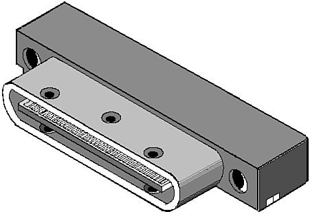
The general rule underlying these recommendations is to divide 30 by the bus clock to derive the maximum recommended cable length in meters. The rule does not apply to Ultra2 SCSI because of the special low-voltage differential signals used under that standard. CablesIn the current SCSI scheme of things, only two different cable types are used. These are designated the A cable and the P cable. The A cable has 50 conductors and serves for all eight-bit SPI systems, both single-ended and differential. Similarly, the 68-conductor P cable serves wide signaling systems. The purpose assigned each conductor in the cable varies with the type of signaling used and the connector system. The allowed variety is wide. In fact, the cable is a minor concern compared to connector considerations. ConnectorsMore than any other standard computer wiring system, SCSI suffers from a plague of connectors. Not only do internal and external devices use different connector styles, but both also come in a wide variety. Beside separate internal and external connector styles, the system also suffers from generational differences. The SPI-3 specifications acknowledge eight connector systemsfour nonshielded alternatives for internal devices and four shielded systems for external devices. In the past, computer-makers have used other designs to suit their particular requirements. Table 10.15 summarizes the SPI connector options. The oldest SCSI devices use 50-pin connectors. More recent devices use 68-pin connectors that support wide as well as narrow SCSI implementations. Many hard disk drives use 80-pin connectors (also called SCA for Single Connector Attachment) that integrate power as well as the SCSI signal onto a single connector, allowing for the easier hot-swapping of devicesin particular, the hard disks used in massive disk arrays (see Chapter 17, "Magnetic Storage"). For the most part, a SCSI connector is like a shoe. If it fits, use it. All too often, however, your SCSI device comes equipped with a connector that looks weirdly different from the one on the cable you're trying to snap onto it. You can prevent problems by checking the connector type used by the SCSI cables in your computer and matching any device you buy to your cabling. SCSI deviceshard disk drives in particularoften have several connector options. When buying a new drive, choose the one that fits. Adapters are also available for matching unlike connectors. Within the limitations noted in the next section, an adapter is often sufficient to get any SCSI device to link up with any host adapter. 50-pin Internal ConnectorsThe initial incarnation of the SCSI interface was the basic 50-contact pin connector used on the first SCSI drives. Officially, this system is termed the nonshielded connector alternative 2. Basically a glorified header, this connector featured two parallel rows of pins in a rectangular array, the centers of the pins separated at increments of 0.1 inch, both horizontally and vertically. Figure 10.7 shows the male connector of this type as you would find it on the rear of a SCSI device. At one time, nearly all SCSI devices that used the eight-bit implementation of the standard used this connector. However, both SPI-2 and SPI-3 offer another 50-pin nonshielded design that's more compact and more consistent with current circuit design practices. Termed the nonshielded connector alternative 1, this design also uses two parallel rows of pins. As with the older connector, the rows are spaced on 0.1-inch centers, but the individual pins in each row are spaced at only half that distance, 0.05 inch. The female receptacle is molded with a vague "D" shape. The male connector has a matching extended D-shaped perimeter that protects the pins. Drives use the female connector as a jack. Figure 10.10 shows this connector. Figure 10.10. The 50-pin nonshielded connector alternative 1.
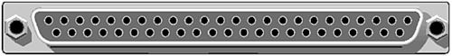
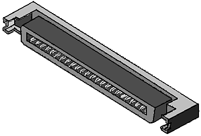
Although both nonshielded connector alternatives 1 and 2 have 50 pins, the functions assigned each pin differ between the two alternatives. In fact, there are four variations: single-ended alternative 1, single-ended alternative 2, differential alternative 1, and differential alternative 2. You cannot tell the four options apart by merely looking at the connector. You must check the specifications of the drive to determine the signal type it uses. 50-pin External ConnectorsThe most common form of external SCSI connectors has 50 pins arranged in two rows of 25 and looks like an enlarged Centronics printer connector. This connector is termed the shielded connector alternative 2 under SPI-2 and SPI-3. It is still the most common 50-pin connector used by external SCSI devices and is shown in Figure 10.11. Figure 10.11. The 50-place ribbon connector, shielded connector alternative 2.
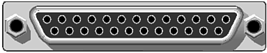
The shielded connector alternative 1 also offers 50-pins to external devices. It uses the same layout and signal system as the alternative 1 nonshielded connector, except the mating portions of the connector are metal shields. Figure 10.12 shows this connector. Figure 10.12. The 50-place external shielded connector alternative 1.
As with the nonshielded 50-pin connectors, shielded connector alternatives 1 and 2 differ in the functions assigned each pin. The pin-outs of the connector alternatives are the same as for the nonshielded versions. Because of the physical similarities and identical pin-outs, you can plug a raw drive into an external shielded alternative 1 connector (providing you don't mix the single-ended and differential signaling systems). The nonshielded and shielded versions of alternative 2 also share the same signal assignments with their pins, but the connectors are physically incompatible. Some older external SCSI devices and host adapters used classic 50-pin D-shell connectors with the same signal assignments as the A connector. They never attracted a following because they were simply ungainly, about four inches long. These resemble the alternative 1 connectors but the pins are round rather than square, more widely spaced, and staggered. Figure 10.13 shows this large connector. Figure 10.13. The nonstandardized 50-pin D-shell connector.
More popular was a design that trimmed the length of the D-shell connector in half by similarly trimming the pin count. These shorter, 25-pin D-shell connectors saved space and were popularized by Apple Computer for its Macintosh equipment. The connectors are identical to those used by most computer-makers for their parallel port connections. Despite the similarity, the signals on the SCSI and parallel ports are entirely different and should never be connected together. To reduce the number of pins required, this style of connector eliminates many of the ground return signals used in single-ended SCSI. These connectors do not have enough connections for differential signals. Figure 10.14 shows this connector. Figure 10.14. The female 25-pin D-shell connector used by some SCSI products.
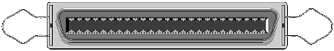
68-pin ConnectorsWide SCSI requires more connections than are possible with a 50-pin connector. To accommodate all the required signals, the SPI standards specify a set of 68-pin connectors. This connector system offers both nonshielded and shielded alternatives for internal and external devices. Both the nonshielded and shielded versions use essentially the same design and the same signal assignments. The chief difference is the roughly D-shaped metal shield surrounding the contacts of both male and female connectors, with the shield also protecting the bare pins of the male connector, much as in a classic D-shell connector. Both connectors are termed alternative 3. That is, the internal set make up nonshielded connector alternative 3, and the external set nonshielded connector alternative 3. Many sources refer to either the shielded or nonshielded connector simply as a SCSI-3 connector. Do not be misled by this label, which is best seen as an abbreviation for SCSI alternative 3 connector. All SCSI-3 systems do not use this connector system. In fact, the SCSI-3 standard allows any of the eight connector alternativesas well as the connectors for the various other physical interconnection systems besides SPI. The pins of the alternative 3 connectors are arranged in two rows of 34 male contacts. The pins within each row are located on 0.05-inch centers, and the two rows are spaced on 0.1-inch centers. Figure 10.15 shows the shielded version of this connector. Figure 10.15. The 68-place shielded connector alternative 3.
The SPI specifications allow for a second style of shielded 68-pin connector that looks like a miniaturized version of the classic 50-place external SCSI ribbon connector. Termed the shielded connector alternative 4, it uses the same pin-out as alternative 3. Instead of pins, it has two rows of ribbon contacts spaced at 0.0315-inch intervals. Figure 10.16 shows this connector. Figure 10.16. Shielded connector alternative 4.
80-pin SCAHot-swapping drives requires that both control signals and drive power be connected quickly and easily. To accommodate the needed power signals, drive-makers developed the 80-pin SCSI connector system. Under the SPI rubric, this is the nonshielded connector alternative 4. Figure 10.17 shows this connector. Figure 10.17. The 80-pin SCA connector.
The SCA connector is designed chiefly for internal usefor sliding drives into racks. There is no external equivalent to the SCA connector. All the pins on the connector on the SCA device are the same length. On the host end, however, several of the pins are extended so that they make contact first when the drive gets plugged in. These longer pins (numbers 1, 3643, 45, 46, and 7880) ground the drive, supply power to it, and set its SCSI ID number. The added length ensures that the drive powers up properly and is properly identified before it presents signals to the bus. Mixing SCSI StandardsSCSI comes in so many flavors that you're likely to have devices that follow two or more standards that you'll want to hook together in a single chain. With modern host adapters that allow you to configure the transfer characteristics assigned to each SCSI ID, you can freely mix standards with a reasonable chance that you can get everything to work together. Better still, you can tune all devices to operate at their maximum transfer rate, with only a few exceptions. In most cases, however, you can't just string together a mixed collection of SCSI peripherals with complete impunity. You still have to consider issues of bus width, signal type (single-ended or differential), and clock speed to make optimal connections. Some things just won't fitand others you may not want to fit. Bus WidthIn theory, you can mix wide (16-bit) and narrow (8-bit) SCSI devices in a single chain. However, you must follow some rules. With an internal chain of mixed devices, the wide ribbon cable carries the full compliment of signals to all the devices in the chain. The last device in the chain (the one that provides the termination) should be wide. You may need an adapter for each narrow SCSI device you want to plug into the wide chain. To mix wide and narrow SCSI devices together in an external SCSI daisy-chain, you need to follow one rule: Wide goes first. The most important rule is that you must chain all of the wide devices together, plugged into the host adapter, then chain the narrow devices after the wide chain. A narrow device won't pass through the signals of a wide device, so any wide device after a narrow one in the chain will lose its wide-bus option. Signaling SystemThe original SCSI specifications allowed for two types of SCSI buses: single-ended and differential. These quite different signaling systems are inherently incompatible. Although adapters help mate them together, dangers remain. For example, connecting a single-ended device such as a CD-ROM drive to a differential host adapter or a differential drive to a single-ended host adapter may physically damage both the host adapter and the drive. Because the SCSI connector system does not distinguish between signal types, you must be sure of the signal types used by all the devices in your SCSI system before making the first connection. The single-ended and high-voltage differential signaling systems are incompatible and cannot be used on the same bus. In addition, high-voltage and low-voltage differential signaling types are also incompatible. Connecting a single HVD device to an LVD system could damage all the LVD devices in the system. In theory, single-ended and LVD devices can be chained together, but you need to be sure the full array of differential signals get to the LVD deviceswhich means not only differential signals but also the wide bus signals for Ultra160 and Ultra320 SCSI, which demand a wide bus for proper operation. Clock SpeedAlthough the different top speeds of SCSI devices might appear to be a problem and limit all the devices, no matter how fast, to the speed constraints of the slowest, the issue never arises. The SCSI host adapter only communicates with a single device at a time, and those communications monopolize the SCSI bus while they are taking place. In today's SCSI systems, transfers do not go directly between devices but instead must travel through the host adapter. For example, to back up a hard disk, the disk first sends a block of data to the host adapter, which temporarily stores the data in system memory. When the disk finishes sending its block, the host adapter moves the data from memory to the tape drive. Consequently, the two SCSI deviceshard disk and tape drivecommunicate with the host adapter independently of one another and may operate at different speeds. A modern host adapter can adjust its speed to suit whatever devices with which it communicates. In general, it will set itself to transfer data to each device at the top speed at which that device can operate. The one big exception to the "any speed" rule is Ultra2 SCSI. Put simply, you cannot attach an ordinary SCSI device to an Ultra2 SCSI port and expect Ultra2 SCSI peripherals to operate at top speed. The issue is not really speed, however. All Ultra2 SCSI devices use LVD signaling. Most ordinary SCSI devices use single-ended (SE) signaling. When you plug an SE device into the Ultra2 bus, the bus reverts to SE operation; otherwise, damage would result. The SCSI host adapter would send the negative-going differential voltages into a direct short-circuit because the associated signal pins are grounded in the single-ended device. Although reverting to single-ended operation minimizes the chance for damage, it also limits the speed potential to ordinary Ultra SCSI because the highest speeds of Ultra2 SCSI require the added integrity of differential signaling. Operation and ArbitrationAll devices connected to a single SCSI bus function independently, under the control of the host system through the SCSI adapter. Rather than just using signals on dedicated conductors on the bus that can be understood by devices as dumb as a light bulb, SCSI presupposes a high degree of intelligence in the devices it connects and provides its own command setessentially, its own computer languagefor controlling these devices. Boot UpMost software drivers search for their target devices when they are booted into your system. Consequently, all your external SCSI devices should be running when you switch on your computer. Turn on your SCSI devices before you switch on your computer, or use a power director (outlet box) that ensures that your entire computer systemcomputer and SCSI peripheralsswitch on simultaneously. ArbitrationNot only is SCSI more like an expansion bus of a computer than a traditional hard disk interface, but it also resembles today's more advanced Micro Channel and NuBus designs. Like the latest computer buses, SCSI provides an arbitration scheme. Arbitration enables the devices connected to the bus to determine which of them can send data across the bus at a given time. Instead of being controlled by the host computer and suffering delays while its microprocessor does other things, the arbitration of the SCSI bus is distributed among all the devices on the bus. Arbitration on the SCSI bus is handled by hardware. Each of the up to seven SCSI devices is assigned a unique identifying number, usually by setting jumpers or DIP switches on the drive in a manner similar to the Drive Select jumpers on an ST506 device. When a device, called the initiator, wants to access the SCSI bus, it waits until the bus is free and then identifies itself by sending a signal down one of the SCSI data lines. At the same time, it transmits a signal down another SCSI data line corresponding to the other SCSI device, called the target, that it wants to interact with. The eight data lines in the SCSI connection allow for the unique identification of seven SCSI devices and one host. Note that SCSI devices can initiate arbitration on their own, independent of the host. Two SCSI devices also can transfer information between one another without host intervention. A SCSI hard disk, for example, may back itself up to a SCSI tape drive without requiring the attention of (and thus robbing performance from) its host computer. Better than background operation, this form of backup represents true parallel processing in the computer system. In addition, SCSI provides for reselecting. That is, a device that temporarily does not need bus access can release the bus, carry out another operation, and then resume control. You can command a disk drive to format, and it can carry out that operation without tying up the bus, for example. The net result is, again, true parallel processing. Because SCSI is a high-level interface, it also isolates the computer from the inner workings of the peripherals connected to it. The SCSI standard allows hard disks to monitor their own bad tracks independently from the computer host. The disk drive reassigns bad tracks and reports back to its computer host as if it were a perfect disk. In addition, hard disk drives can be designed to automatically detect sectors that are going bad and reassign the data they contain elsewhere, all without the host computer or the user ever being aware of any problems. Sanctioning OrganizationThe American National Standards Institute (ANSI) maintains the official SCSI standards. SCSI standards in their final, published form are available only from ANSI. The SCSI T10 Committee actively develops the various SCSI standards. It provides recommendations to ANSI, which, on its approval, sanctions the specifications as industry standards. The committee acts as a forum for introducing and discussing proposals for the standards. The committee maintains a Web address at www.symbios.com/t10. The SCSI Trade Association promotes the use of SCSI and devices that adhere to that standard. The association maintains a Web site at www.scsita.org. |
||||||||||||||||||||||||||||||||||||||||||||||||||||||||||||||||||||||||||||||||||||||
| [ Team LiB ] |
|