| [ Team LiB ] |
|
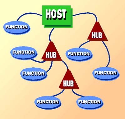
Universal Serial BusIn 1995, Compaq, Digital, IBM, Intel, Microsoft, NEC, and Northern Telecom, determined to design a better interface, pooled their efforts and laid the groundwork for the Universal Serial Bus, better known as USB. Later that year, they started the Universal Serial Bus Implementers Forum and in 1996 unveiled the new interface to the world. The world yawned. Aimed at replacing both legacy serial and parallel port designs, the USB design corrected all three of their shortcomings. To improve performance, they designed USB with a 12Mbps data rate (with an alternative low-speed signaling rate of 1.5Mbps). To eliminate wiring hassles and worries about connector gender, crossover cables, and device types, they developed a strict wiring system with exactly one type of cable to serve all interconnection needs. And to allow one jack on the back of a computer to handle as many peripherals as necessary, they designed the system to accommodate up to 127 devices per port. In addition, they built in Plug-and-Play support so that every connection could be self-configuring. You could even hot-plug new devices and use them immediately without reloading your operating system. On April 27, 2000, a new group, led by Compaq, Hewlett-Packard, Intel, Lucent, Microsoft, NEC, and Philips, published a revised USB standard, version 2.0. The key change was an increase in performance, upping the speed from 12Mbps to 480Mbps. The new system incorporates all the protocols of the old and is fully backward compatible. Devices will negotiate the highest common speed and use it for their transfers. Connectors and cabling remained unchanged. BackgroundDesigned for those who would rather compute than worry about hardware, the premise underlying USB is the substitution of software intelligence for cabling confusion. USB handles all the issues involved in linking multiple devices with different capabilities and data rates with a layer-cake of software. Along the way, it introduces its own new technology and terminology. USB divides serial hardware into two classes: hubs and functions. A USB hub provides jacks into which you can plug functions. A USB function is a device that actually does something. USB's designers imagined that a function may be anything you can connect to your computer, including keyboards, mice, modems, printers, plotters, scanners, and more. Rather than a simple point-to-point port, the USB acts as an actual bus that allows you to connect multiple peripherals to one jack on your computer with all the linked functions (devices) sharing exactly the same signals. Information passes across the bus in the form of packets, and all functions receive all packets. Your computer accesses individual functions by adding a specific address to the packets, and only the function with the correct address acts on the packets addressed to it. The physical manifestation of USB is a porta jack on the back of your computer or in a hub. Although your computer's USB port can handle up to 127 devices, each physical USB port connects to a single device. To connect multiple devices, you need multiple jacks. Typically, a new computer comes equipped with two USB ports. When you need more, you add a hub, which offers multiple jacks to let you plug in several devices. You can plug one hub into another to provide several additional jacks and ports to connect more devices. The USB design envisions a hierarchical system with hubs connected to hubs connected to hubs. In that each hub allows for multiple connections, the reach of the USB system branches out like a treeor a tree's roots. Figure 11.1 gives a conceptual view of the USB wiring system. Figure 11.1. The USB hierarchical interconnection scheme.
Your computer acts as the base hub for a USB system and is termed the host. The circuitry in your computer that controls this integral hub and the rest of the USB system is called the buscontroller. Each USB system has one and only one bus controller. Under USB 2.0, a device can operate at any of three speeds: Low speed is 1.5Mbps. Full speed is 12Mbps, and high speed is 480Mbps. USB 2.0 is backward compatible with USB 1.1all USB 1.1 devices will work with USB 2.0 devices, and vice versa, but USB 1.1 will impose its speed limit on USB 2.0 devices. The mixing of speeds makes matters complicated. If you plug both a USB 2.0 and a USB 1.1 device into a USB 2.0 hub, both devices will operate at their respective top speeds. But if a USB 1.1 hub appears in the chain between USB 2.0 devices, the slower hub will limit the speed of the overall system. Plug any USB 2.0 device into a USB 1.1 hubeven a USB 2.0 huband it will degrade to USB 1.1 operation (and if it's a hub, so will all the devices connected to that hub). Other than this speed issue, the USB system doesn't care which device you plug into which hub or how many levels down the hub hierarchy you put a particular device. All the system requires is that you properly plug everything together following its simple rule: Each device must plug into a hub. The USB software then sorts everything out. This software, making up the USB protocol, is the most complex part of the design. In comparison, the actual hardware is simplebut the hardware won't work without the protocol. The wiring hardware imposes no limit on the number of devices/functions you can connect in a USB system. You can plug hubs into hubs into hubs, fanning out into as many ports as you like. You do face limits, however. The protocol constrains the number of functions on one bus to 127 because of addressing limits. Seven bits are allowed for encoding function addresses, and one of the potential addresses (128) is reserved. In addition, the wiring limits the distance at which you can place functions from hubs. The maximum length of a USB cable is five meters. Because hubs can regenerate signals, however, your USB system can stretch out for greater distances by making multiple hops through hubs. As part of the Plug-and-Play process, the USB controller goes on a device hunt when you start up your computer. It interrogates each device to find out what it is. It then builds a map that locates each device by hub and port number. These become part of the packet address. When the USB driver sends data out the port, it routes that data to the proper device by this hub-and-port address. USB requires specific software support. Any device with a USB connector will have the necessary firmware to handle USB built in. But your computer will also require software to make the USB system work. Your computer's operating system must know how to send the appropriate signals to its USB ports. All Windows versions starting with Windows 98 have USB support. Windows 95 and Windows NT do not. In addition, each function must have a matching software driver. The function driver creates the commands or packages the data for its associated device. An overall USB driver acts as the delivery service, providing the channelin USB terminology, a pipefor routing the data to the various functions. Consequently, each USB you add to your computer requires software installation along with plugging in the hardware. ConnectorsThe USB system involves four different styles of connectorstwo chassis-mounted jacks and two plugs at the ends of cables. Each jack and plug comes in two varieties: A and B. Hubs have A jacks. These are the primary outward manifestation of the USB portthe wide, thin USB slots you'll find on the back of your computer. The matching A plug attaches to the cable that leads to the USB device. In the purest form of USB, this cable is permanently affixed to the device, and you need not worry about any other plugs or jacks. This configuration may someday become popular when manufacturers discover they can save the cost of a connector by integrating the cable. Unfortunately, too many manufacturers have discovered that by putting a jack on their USB devices they save the cost of the cable by not including it with the device. To accommodate devices with removable cables (and manufacturers that don't want the add the expense of a few feet of wire to their USB devices), the USB standard allows for a second, different style of plug and jack meant only to be used for inputs to USB devices. If a USB device (other than a hub) requires a connector so that, as a convenience, you can remove the cable, it uses a USB B jack, which is a small, nearly square hole into which you slide the mating B plug. The motivation behind this multiplicity of connectors is to prevent rather than cause confusion. All USB cables will have an A plug at one end and a B plug at the other. One end must attach to a hub and the other to a device. You cannot inadvertently plug things together incorrectly. Because all A jacks are outputs and all B jacks are inputs, only one form of detachable USB cable existsone with an A plug at one end and a B plug at the other. No crossover cables or adapters are needed for any USB wiring scheme. CableThe USB system uses two kinds of cablethat meant for low-speed connections and that meant for full- and high-speed links. But you only have to worry about the higher-speed variety. Low-speed cables, those capable of supporting only 1.5Mbps signaling rates, must be permanently attached to the equipment using them. Higher-speed cables can be either permanently attached or removable. Both speeds of physical USB wiring use a special four-wire cable. Two conductors in the cable transfer the data as a differential digital signal. That is, the voltage on the two conductors is of equal magnitude and opposite polarity so that when subtracted from one another (finding the difference) the result cancels out any noise that ordinarily would add equally to the signal on each line. In addition, the USB cable includes a power signal, nominally five-volts DC, and a ground return. The power signal allows you to supply power for external serial devices through the USB cable. The two data wires are twisted together as a pair. The power cables may or may not be. The difference between low- and higher-speed cables is that the capacitance of the low-speed cable is adjusted to support its signaling rate. In addition, the low speed does not need twisted-pair wires, and the standard doesn't require them. All removable cables must be able to handle both full-speed and high-speed connections. To achieve its high data rate, the USB specification requires that certain physical characteristics of the cable be carefully controlled. Even so, the maximum length permitted for any USB cable is five meters. One limit on cable length is the inevitable voltage drop suffered by the power signal. All wires offer some resistance to electrical flow, and the resistance is proportional to the wire gauge. Hence, lower wire gauges (thicker wires) have lower resistance. Longer cables require lower wire gauges. At maximum length, the USB specification requires 20-gauge wire, which is one step (two gauge numbers) thinner than ordinary lamp cord. The individual wires in the USB cable are color-coded. The data signals form a green-white pair, with the +Data signal on green. The positive five-volt signal rides on the red wire. The ground wire is black. Table 11.2 sums up this color code.
Normally, you cannot connect one computer to another using USB. The standard calls for only one USB controller in the entire interconnection system. Physically the cabling system prevents you from making such a connection. The exception is that some cables have a bridge built in that allows two USB hosts to talk to each other. The bridge is active circuitry that converts the signals. ProtocolAs with all more recent interface introductions, the USB design uses a packet-based protocol using No Return-to-Zero Inverted (NRZI) data coding. All message exchanges require the swapping of three packets. The exchange begins with the host sending out a token packet. The token packet bears the address of the device meant to participate in the exchange as well as control information that describes the nature of the exchange. A data packet holds the actual information that is to be exchanged. Depending on the type of transfer, either the host or the device will send out the data packet. Despite the name, the data packet may contain no information. Finally, the exchange ends with a handshake packet, which acknowledges the receipt of the data or other successful completion of the exchange. A fourth type of packet, called Special, handles additional functions. Each packet starts with two componentsa Sync Field and a Packet Identifiereach one byte long. The Sync Field is a series of bits that serves as a consistent burst of clock pulses so that the devices connected to the USB bus can reset their timing and synchronize themselves to the host. The Sync Field appears as three on/off pulses followed by a marker two pulses wide. The Packet Identifier byte includes four bits to define the nature of the packet itself and another four bits as check-bits that confirm the accuracy of the first four. The four bits provide a code that allows for the definition of 16 different kinds of packets. USB uses the 16 values in a two-step hierarchy. The two more significant bits specify one of the four types of packets. The two lesser significant bits subdivide the packet category. Table 11.3 lists the PIDs of the four basic USB packet types.
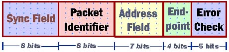
Token PacketsOnly the USB host sends out token packets. Each token packet takes up four bytes, which are divided up into five functional parts. Figure 11.2 graphically shows the layout of a token packet. Figure 11.2. Functional parts of a USB Token Packet.
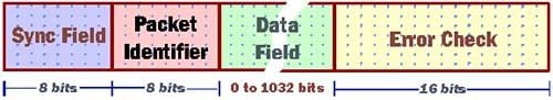
The two bytes take the standard form of all USB packets. The first byte is a Sync Field that marks the beginning of the token's bit-stream. The second byte is the Packet Identifier. The PID byte defines four types of token packets. These include an Out packet that carries data from the host to a device; an In packet that carries data from the device to the host; a Setup packet that targets a specific endpoint; and a Start of Frame packet that helps synchronize the system. Data PacketsThe actual information transferred through the USB system takes the form of data packets. As with all USB packets, a data packet begins with a one-byte Sync Field followed by the Packet Identifier. The actual data follows as a sequence of 0 to 1,023 bytes. A two-byte cyclic redundancy check verifies the accuracy of only the Data Field, as shown in Figure 11.3. The PID field relies on its own redundancy check mechanism. Figure 11.3. Constituents of a USB data packet.
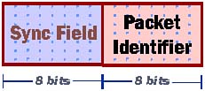
Handshake PacketsHandshake packets handle flow-control in the USB system. All are two bytes long, comprised of nothing more than the Sync Field and a Packet Identifier byte that acknowledges proper receipt of a packet, as shown in Figure 11.4. Figure 11.4. Constituents of a USB handshake packet.
StandardThe USB standard is maintained by USB Implementers Forum. You can download a complete copy of the current version of the specifications from the USB Website.
|
| [ Team LiB ] |
|