| [ Team LiB ] |
|
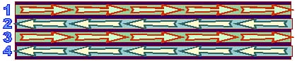
TapeTape was the first magnetic mass storage system used in computers, harking back to the days of room-size Univacs and vacuum tubes. It first proved itself as a convenient alternative to punched cards and punched paper tapethe primary storage system used by mainframe computers. Later, information transfer became an important use for tape. Databases could be moved between systems as easily as carting around one or more spools of tape. After magnetic disks assumed the lead in primary storage, tape systems were adapted to backing them up. As a physical entity, tape is both straightforward and esoteric. It is straightforward in design, providing the perfect sequential storage mediuma long, thin ribbon that can hold orderly sequences of information. The esoteric part involves the materials used in its construction. The tape used by any system consists of two essential layersthe backing and the coating. The backing provides the support strength needed to hold the tape together while it is flung back and forth across the transport. Progress in the quality of the backing material mirrors developments in the plastics industry. The first tape was based on paper. Shortly after the introduction of commercial tape recorders at the beginning of the 1950s, cellulose acetate (the same plastic used in safety film in photography for three decades previously) was adopted. The state-of-the-art plastic is polyester, of double-knit leisure-suit fame. In tape, polyester has a timeless style of its ownflexible and long-wearing with a bit of stretch. It needs all those qualities to withstand the twists and turns of today's torturous mechanisms, fast shuttle speeds, and abrupt changes of direction. The typical tape backing measures from one-quarter mil (thousandth of an inch) to one mil thick, about 10 to 40 microns. The width of the backing varies with its intended application. Wider tapes offer more area for storing data but are most costly and, after a point, become difficult to package. The narrowest tape in common use, cassette tape, measures 0.150 inches (3.8 millimeters) wide. The widest in general use for computing measures 0.5 inches (12.7 millimeters). Equipment design and storage format determine the width of tape to be used. Coatings have also evolved over the decades, as they have for all magnetic media. Where once most tapes were coated with doped magnetic oxides, modern coatings include particles of pure metal in special binders and even vapor-plated metal films. Tape coatings are governed by the same principles as other magnetic media; the form is different but the composition remains the same. As with all magnetic storage systems, modern tape media have higher coercivities and support higher storage densities. Taken by itself, tape is pretty hard to get a handle on. Pick up any reasonable length of tape, and you'll have an instant snarl on your hands. The only place that tape is used by itself is in endless loops (one end spliced to the other) in special bins used by audio and video duplicating machines. In all other applications, the tape is packaged on reels or in cartridges. Reels came first. A simple spool onto which a length of tape gets wound, the reel is the simplest possible tape carrier. In this form, tape is called open reel. Putting tape in a cartridge adds a permanent package that both provides protection to the delicate medium and makes it more convenient to load. The most basic cartridge design simply packages a reel of tape in a plastic shell and relies on an automatic threading mechanism in the drive itself. All current computer-size tape systems use a more sophisticated designcassette-style cartridges that include both the supply and take-up reels in a single cartridge. The basic cassette mechanism simply takes the two spools of the open-reel tape transport and puts them inside a plastic shell. The shell protects the tape because the tape is always attached to both spools, eliminating the need for threading across the read/write heads and through a drive mechanism. The sides of the cassette shell serve as the sides of the tape reelholding the tape in place so that the center of the spool doesn't pop out. This function is augmented by a pair of Teflon slip-sheets, one on either side of the tape inside the shell, that help to eliminate the friction of the tape against the shell. A clear plastic window in either side of the shell enables you to look at how much tape is on either spoolhow much is left to record on or play back. The reels inside the cassette are merely hubs that the tape can wrap around. A small clip that forms part of the perimeter of the hub holds the end of the tape to the hub. At various points around the inside of the shell, guides are provided to ensure that the tape travels in the correct path. More recent tape cartridges have altered some of the physical aspects of the cassette design but retain the underlying technologies. TechnologiesTape systems are often described by how they workthat is, the way they record data onto the tape. For example, although the term streaming tape that's appended to many tape drives may conjure up images of a cassette gone awry and spewing its guts inside the dashboard of your card (and thence to the wind as you fling it out the window), it actually describes a specific recording mode that requires an uninterrupted flow of data. At least four of these termsstart-stop, streaming, parallel, and serpentinecrop up in the specifications of common tape systems for computers. Start-Stop TapeThe fundamental difference between tape drives is how they move the tape. Early drives operated in start-stop modethey handled data one block (ranging from 128 bytes to a few kilobytes) at a time and wrote each block to the tape as it was received. Between blocks of data, the drive stopped moving the tape and awaited the next block. The drive had to prepare the tape for each block, identifying the block so that the data could be properly recovered. Watch an old movie with mainframe computers with jittering tape drives, and you'll see the physical embodiment of start-stop tape. Streaming TapeWhen your computer tape drive gets the data diet it needs, bytes flow to the drive in an unbroken stream and the tape runs continuously. Engineers called this mode of operation streaming tape. Drives using streaming tape technology can accept data and write it to tape at a rate limited only by the speed the medium moves and the density at which bits are packedthe linear density of the data on the tape. Because the tape does not have to stop between blocks, the drive wastes no time. Parallel RecordingJust as disk drives divide their platters into parallel tracks, the tape drive divides the tape into multiple tracks across the width of the tape. The number of tracks varies with the drive and the standard it follows. The first tape machines used with computer systems recorded nine separate data tracks across the width of the tape. The first of these machines used parallel recording, in which they spread each byte across their tracks, one bit per track, with one track for parity. A tape was good for only one pass across the read/write head, after which the tape needed to be rewound for storage. Newer tape systems elaborate on this design by laying 18 or 36 tracks across a tape, corresponding to a digital word or double word, written in parallel. Parallel recording provides a high transfer rate for a given tape speed because multiple bits get written at a time but makes data retrieval time consumingfinding a given byte might require fast forwarding across an entire tape. Serpentine RecordingMost computer tape systems use multitrack drives but do not write tracks in parallel. Instead, they convert the incoming data into serial form and write that to the tape. Serial recording across multiple tracks results in a recording method called serpentine recording. Serpentine cartridge drives write data bits sequentially across the tape in one direction on one track at a time, continuing for the length of the tape. When the drive reaches the end of the tape, it reverses the direction the tape travels and cogs its read/write head down one step to the next track. At the end of that pass, the drive repeats the process until it runs out of data or fills all the tracks. Figure 17.4 shows the layout of tracks across a tape using four tracks of serpentine recording. Figure 17.4. Layout of four tracks using serpentine recording.
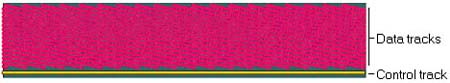
A serpentine tape system can access data relatively quickly by jogging its head between tracks, because it needs to scan only a fraction of the data on the tape for what you want. Additionally, it requires only a single channel of electronics and a single pole in the read/write head, thus lowering overall drive costs. Modern serpentine systems may use over 50 tracks across a tape. Helical RecordingThe basic principle of all the preceding tape systems is that the tape moves past a stationary head. In a helical scan recording system, both the head and tape move. Usually multiple rotating heads are mounted on a drum. The tape wraps around the drum outside its protective cartridge. Two arms pull the tape out of the cartridge and wrap it about halfway around the drum (some systems, like unlamented Betamax, wrap tape nearly all the way around the drum). So that the heads travel at an angle across the tape, the drum is canted at a slight angle, about five degrees for eight-millimeter drives and about six degrees for DAT. The result is that a helical tape has multiple parallel tracks that run diagonally across the tape instead of parallel to its edges. These tracks tend to be quite finesome helical systems put nearly 2000 of them in an inch. In most helical systems, the diagonal tracks are accompanied by one or more tracks parallel to the tape edge used for storing servo control information. In video systems, one or more parallel audio tracks may also run the length of the tape. Figure 17.5 shows how the data and control tracks are arranged on a helical tape. Figure 17.5. Helical scan recording track layout.
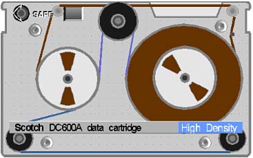
Helical scan recording can take advantage of the entire tape surface. Conventional stationary-head recording systems must leave blank areasguard bandsbetween the tracks containing data. Helical systems can and do overlap tracks. Although current eight-millimeter systems use guard bands, DAT writes the edges of tracks over one another. This overlapping works because the rotating head drum actually has two (or more) heads on it, and each head writes data at a different angular relationship (called the azimuth) to the tracks on the tape. In reading data, the head responds strongly to the data written at the same azimuth as the head and weakly at the other azimuth. In DAT machines, one head is skewed 20 degrees forward from perpendicular to its track; the other head is skewed backward an equal amount. FormatsEach of these various recording methods, along with physical concerns such as tape width and cartridge design, allow for a nearly infinite range of tape-recording systems. When you try to make sense of backup systems, it often seems like all the possibilities have been tried in commercial products. Linear Recording Tape SystemsThe most straightforward tape systems use simple linear recording. That is, they move the tape past a stationary head just like the very first audio tape recorders. Linear recording is the old reliable in tape technology. The process and methods have been perfected (as much as that is possible) over more than five decades of use. Open-reel tape is still used in computer systems, but most personal computers use more modern, more compact, and more convenient cassette-style cartridges. The most common of these are patterned after a design the 3M Company first offered using quarter-inch tape as a data-recording medium. First put on the market in 1972, these initial quarter-inch cartridges were designed for telecommunications and data-acquisition applications calling for the storage of serial data, such as programming private business telephone exchanges and recording events. Compared to the cassette, the tape cartridge requires greater precision and smoother operation. To achieve that end, a new mechanical design was invented by Robert von Behren of the 3M Company, who patented it in 1971the quarter-inch cartridge mechanism. Instead of using the capstan drive system like cassettes, the quarter-inch cartridge operates with a belt drive system. A thin, isoelastic belt stretches throughout the cartridge mechanism, looping around (and making contact with) both the supply and take-up spools on their outer perimeters. The belt also passes around a rubber drive wheel, which contacts a capstan in the tape drive. The capstan moves the belt but is cut away with a recess that prevents it from touching the tape. The friction of the belt against the outside of the tape reels drives the tape. This system is gentler to the tape because the driving pressure is spread evenly over a large area of the tape instead of pinching the tape tightly between two rollers. In addition, it provides for smoother tape travel and packing of the tape on the spools. The tape is wound, and the guide and other parts of the mechanism arranged so that the fragile magnetic surface of the tape touches nothing but the read/write head (see Figure 17.6). Figure 17.6. Quarter-inch cartridge mechanisms (DC-600 style cartridge is shown; the DC2000 is similar but smaller).
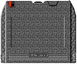
For sturdiness, the cartridge is built around an aluminum baseplate. The rest of the cartridge is transparent plastic, allowing the condition of the tape and the mechanism to be readily viewed. To try to lessen the chaos in the tape cartridge marketplace, a number of tape drive manufacturersincluding DEI, Archive, Cipher Data, and Tandbergmet together at the National Computer Conference in Houston in 1982. They decided to form a committee to develop standards so that a uniform class of products could be introduced. The organization took the name, Working Group for Quarter-Inch Cartridge Drive Compatibility, often shortened into QIC committee. In November, 1987, the organization was officially incorporated as Quarter-Inch Cartridge Standards, Inc. QIC developed a number of standards for data cartridges. But as personal computers became popular, most tape companies realized that the cartridges were just too big. Squeezing a drive to handle a six-by-four cartridge into a standard 5.25-inch drive bay is a challenge; fitting one in a modern 3.5-inch bay is impossible. Seeking a more compact medium, quarter-inch cartridge makers cut their products down to size, reducing tape capacity while preserving the proven drive mechanism. The result was the mini-cartridge. QIC quickly developed standards for the new cartridge. Because the 3M Company introduced the first mini-cartridge with the designation DC2000, many people in the computer industry persist in calling all mini-cartridges "DC2000-style" cartridges. Mini-cartridges actually come in a variety of designations. As with the current model numbers of DC600-size cartridges, the model designations of most mini-cartridges encode the cartridge capacity as their last digits. For example, a DC2080 cartridge is designed for 80MB capacity; a DC2120 for 120MB. One big advantage of the smaller cartridges is that drives for them easily fit into standard 3.5-inch bays. The mini-cartridge package measures just under 3.25x2.5x0.625 inches. As originally developed, it held 205 feet of tape with the same nominal quarter-inch width used by larger cartridges, hence the initial "2" in the designation. After trying to exploit the compact size of the mini-cartridge for years, media-makers decided they had gone too far. They cut too much capacity from their cartridges. Therefore, they added some extra inches back on the back of the cartridges so that the cartridges would still slide into smaller drives but could hold more tape. Two formats developed: Travan and QIC-EX. TravanIn 1995, tape- and drive-makers pushed mini-cartridges to yet higher capacities with the simple expedient of making the cartridges bigger so that they could hold more tape. The fruit of the labors of an industry group comprising Conner, Iomega, HP, 3M Company, and Sony was called Travan technology. The increase in cartridge size appears in three dimensions. The cartridges are both wider, deeper, and taller. The added height allows the use of wider tape, the same eight-millimeter (0.315-inch) tape used by the QIC-Wide format, the format pioneered by Sony. The wider tape permits an increase in track count by about 30 percent (from 28 to 36 in the initial Travan format). In addition, Travan adds an extra half-inch to the width and depth of cartridges. The Travan cartridge measures 0.5x3.6x2.8 inches (HWD), smaller in the front (3.2 inches) than the rear, where the tape spools reside. Internally, the Travan cartridge uses the same 3M mechanism as other quarter-inch cartridges and must be formatted before use. Although the increase seems modest, it allows the tape capacity to more than double, from 307 feet in a DC2120 cartridge to 750 feet in the Travan. The extra size gives Travan a distinctive shape, basically rectangular with two corners curved in to make sliding in a cartridge easier. Figure 17.7 shows a Travan cartridge. Figure 17.7. A Travan tape cartridge.
The combination of more tracks and greater tape length was sufficient to boost single cartridge capacity to 400MB (uncompressed) in the initial Travan implementation. Nothing about the Travan design impairs making further improvements, so whatever developments add to the capacity of standard mini-cartridges can be directly reflected in increased Travan capacities. In fact, since its introduction, Travan has been improved three times, each change about doubling single-cartridge capacities. The first change, creating TR-2, boosted the coercivity of the medium and allowed for a 50-percent increase in data density, both in a greater number of tracks and a higher linear density on each track. The next change doubled linear density again, without altering the track count, to create TR-3. Another increase in linear density and matching increase in track count boosted the TR-4 Travan implementation to 4GB per cartridge. Table 17.7 summarizes the characteristics of the various Travan implementations.
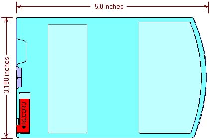
Perhaps the most notable part of the Travan design is its compatibility: A Travan drive accepts standard DC2000 cartridges and QIC-Wide cartridges as well as its own native mediathat's two different cartridge sizes and tape widths in one drive. Compatibility extends to both reading and writing all three cartridge styles. The various Travan implementations also feature backward compatibility. The more recent standards can read tapes made under the earlier Travan standards. QIC-EXAs long as the cartridge in a QIC drive sticks out like Travan, you might as well let it all hang out. That dated cliché underlies the philosophy of QIC-EX. By allowing a cartridge to stick nearly three inches out of the drive, QIC-EX accommodates up to 1000 feet of tape in the QIC format. That's more than double the capacity of ordinary mini-cartridges. Increase the tape width to QIC-Wide's eight millimeters, and you can fit gigabytes onto a standard tape cartridge, as shown in Figure 17.8. Figure 17.8. Dimensions of a QIC-EX tape cartridge.
Unlike Travan, which requires a wider drive with a wider throat to accommodate the wider cartridges, the QIC-EX design is the same width as standard mini-cartridges. QIC-EX tapes consequently fit into most mini-cartridge drives to give an instant capacity increase. Helical-Scan SystemsAlthough helical-scan recording was originally designed for video signals, it is also an excellent match for digital data. The high tape-to-head speed can translate to high data-transfer rates. Although the narrow data tracks devote but a small area of recording medium to storing information, so small that it increases the noise content of the recorded signal, digital technology handily avoids the noise. As with all digital signals, the electronics of the helical-scan tape system simply ignore most of the noise, and error correction takes care of anything that can't be ignored. Helical-scan systems are the children of the digital age. They trade the mechanical precision required in the linear-scan systems for servo-controlled designs. Servo-mechanisms in the helical-scan recorder control both the tape speed and head speed to ensure that the read/write head exactly tracks the position of the tracks on the tape. Although servo-electronics can be built with other technologies, digital electronics and miniaturization make the required circuitry trivial, a single control chip. Moreover, servo-control automatically compensates for inaccuracies in the operation and even construction of the tape-transport system. This design allows manufacturers to use less expensive fabrication processes and helps the mechanism age gracefully, adjusting itself for the wear and tear of old age. Three different helical-scan systems are currently used in tape systems for digital data: eight-millimeter tape, four-millimeter tape (which is formally called the Digital Data Standard), and a proprietary system sold by Pereos. Eight MillimeterProbably the most familiar incarnation of eight-millimeter tape is in miniaturized camcorders. Sony pioneered the medium as a compact, high-quality video-recording system. The same tapes were later adapted to data recording by Exabyte Corporation and first released on the computer market in 1987. In the original Exabyte eight-millimeter digital recording system, the head drum rotated at 1800 revolutions per minute while the tape traveled past it at 10.89 millimeters per second to achieve a track density of 819 per inch and a flux density of 54 kilobits per inchenough to squeeze 2.5MB on a single cartridge. Improvements extended the capacity to 5MB without compression and up to 10GB with compression. The tape can be rapidly shuttled forward and backward to find any given location (and block of data) within about 15 seconds. Eight-millimeter drives tend to be quite expensive. Complete systems cost thousands of dollars. A raw drive alone starts at over one thousand dollars. Its primary market is backing up file servers, machines that can benefit from its huge capacity. Advanced Intelligent TapeSony developed an alternative eight-millimeter technology. By incorporating nonvolatile RAM memory into the shell of an eight-millimeter tape, a tape drive can quickly retrieve directory information without the need to scan the tape. It doesn't have to read the tape at all to find out what's there. This memory is what makes Sony's Advanced Intelligent Tape so smart. Each cartridge has 16KB for storing table of contents and file-location information. Each cartridge can store 25MB of uncompressed data. With data compression the AIT system can achieve transfer rates of 6MBps and a capacity of 50MB per cartridge. Despite being based on eight-millimeter technology, AIT is not backward compatible with the older medium. AIT drives reject conventional eight-millimeter tapes as unsupported media, and hardware write-protection prevents older drives from altering AIT tapes. Digital Data StorageDeveloped originally as a means to record music, the Digital Data Storage first saw commercial application as Digital Audio Tape (DAT), a name sometimes applied to the system even when it is used for storing computer data. The technology was first released as a computer storage medium in 1989. Using a tape that's nominally four millimeters wide (actually 3.81 mm or 0.150 in, the same as cassette tape), the system is sometimes called four-millimeter tape. The thin tape fits into tiny cartridges to store huge amounts of data. The first DAT system could pack 1.3GB into a cassette measuring only 0.4 x 2.9 x 2.1 inches (HWD). The result was, at the time, the most dense storage of any current computer tape medium, 114 megabits per square inch on special 1450 oersted metal particle tape (the same material as used by eight-millimeter digital tape systems). A cassette held either 60 or 90 meters of this tape. The shorter tapes stored 1.3GB; the longer tapes, 2.0GB. Under the aegis of Hewlett-Packard and Sony Corporation, in 1990 this format was formalized as DDS, sometimes listed as DDS-1 (to distinguish it from its successors). The same format underlies DDS-DC, which adds data compression to the drive to increase capacity. Although DDS at first was listed in some literature (and in an earlier edition of this book) as an abbreviation for Digital Data Standard, the DDS organization that coordinates the specification renders it officially as Digital Data Storage. In 1993, the same companies updated the standard to DDS-2, doubling both the data-transfer speed and capacity of the system as well as introducing new 120-meter cassettes using a tape coated with a metal powder medium. In 1995, the standard got upped again to DDS-3, which can pack up to 12GB on each cartridge or 24GB of compressed data. In addition, the DDS-3 standard allows for transfers at double the DDS-2 rate with speed potential of up to 1.5 megabits per second (discounting the effects of compression). DDS-3 uses the same tape media as its predecessor format but increases the data density to 122 kilobits per inch. The key to this higher density is a new technology termed Partial Response Maximum Likelihood (PRML). Announced in 1998, DDS-4 further enhances the four-millimeter format to provide 20GB of storage on a single tape. Part of the capacity increase results from longer tapes, up to 155 meters per cartridge. In addition, DDS-4 reduces track width by 25 percent. Because of its higher data density, DDS-4 also gains a bit of speed. The standard allows for transfer rates from 1 to 3Mbps. DDS-5, originally planned for the year 2001, aimed for a native capacity of 40GB per cartridge but has yet to be formally released. The DDS Web site has not been updated since 1999. Table 17.8 summarizes the various DDS implementations.
In a DDS drive, the tape barely creeps along, requiring about three seconds to move an incha tape speed of 8 millimeters per second. The head drum, however, spins rapidly at 2000 revolutions per minute, putting down 1869 tracks across a linear inch of tape with flux transitions packed 61 kilobits per inch. The first DAT systems shared tapes with audio DAT recorders. Since that time, however, the later DDS standards have required improved magnetic media with higher coercivities. As a result, to get the highest reliability you must use a tape made to the standard that matches your drive. Although you may be able to read older tapes in a later DDS drive, successful writing (where coercivity comes into play) is less probable. Similarly, DDS tape will not work in your DAT recorder. The DDS Manufacturers Group, the organization that coordinates DDS activities, has also developed a technology called Media Recognition System that is able to detect audio DAT tapes. The DDS organization has developed distinctive logos for each level of the DDS hierarchy so that you can readily distinguish tapes and drives. Figure 17.9 shows the logos for DDS-2 through DDS-4. Figure 17.9. The official DDS-2, DDS-3, and DDS-4 logos.
Hewlett-Packard and Sony hold intellectual property rights to DDS technology, and all drives using DDS must be licensed by them. The DDS Manufacturers Group maintains a Web site at www.dds-tape.com. Alas, all tape technologies have lost their luster. They are all hard-pressed to keep up with the huge increases in disk storage densities and capacities. The tape systems with adequate capacity for backing up today's hard disk drives cost more than most personal computers. Consequently, most individual users prefer other backup methods, such as extra hard disks, networked storage (including backing up over the Internet), DVD recorders, and simply ignoring the need for backing up. Data centers rely on a few super-capacity backup systems that are priced well beyond the reach of individuals. Tape is therefore not quite dead. You can use either a mini-cartridge or DDS system for backing up a few gigabytes (about 20GB without compression with today's drives). That should be sufficient for keeping a spare copy of your personal files (including such megabyte-hogs as Computer-Aided Design drawings, graphics, and videos). However, DVD is probably the best, lowest-cost bet for backup today. |
| [ Team LiB ] |
|