| [ Team LiB ] |
|
Electrical FunctionIn the macroscopic world in which we live, switches operate positively without hesitation or doubt. Switch on a light, and it comes on like, well, a light. In the realm of microelectronics, however, switches are not so certain in their first steps toward changing state. As a switch makes contact, it hesitates, letting tiny currents flow and then halting them; then letting more flow. These initial jitters are called switch bounce, and they result from a number of causes. The contact materials of most switches are far from perfect. They may become coated with oxidation or other impurities, and they often don't mesh together perfectly. The contacts touch, bounce, cut through the crud, and finally mate firmly together. In the process, many tiny pulses of electricity can slip through. These pulses aren't enough to affect a light bulb but can be more than sufficient to confuse a semiconductor circuit. For use in computer circuits, switches require special electronics to remove the jitters, to "debounce" their contacts. Such debouncing circuits monitor the switch contacts and change the hesitating initial stabs at changing state into a sharp, certain switch. Unfortunately, each switch contact requires its own debouncer. This is not much of a concern with a single switch, but it can be a nightmare for the designer who must debounce the 101 switches in a typical keyboard. Instead of individual debouncing, computer keyboards use a different process for eliminating the hesitation from keyboard switches. The keyboard electronics do not detect when each switch changes but rather check periodically to see whether a switch has changed. When the electronics note a change in the state of a switch corresponding to the press of a key, they generate an indication of the switch switching that is sent along to your computer. This process has its own shortcomings. The go-and-look method of detection adds a brief wait to signaling each keypress. Moreover, each and every key must be individually checked. But the high speed of today's computer circuits makes this system entirely workable. The process is reduced to a routinethe keyboard electronics scan each key at rates approaching a million times every second, looking for a change in the state of any key. In general, a microprocessor (an 8048-series device in the most popular keyboards) scans the keyboard for current changes every few microseconds, and the minute current flow caused by a keystroke can be detected. Because a slight chance exists that random noisethe stuff that must be debounced awaycould cause a current pulse similar to that generated by a keystroke, keyboards may require that the increased current flow be detected during two or more consecutive scans of the keyboard. In today's computers, the keyboard can use either of two technologies to relay the effects of your keypresses to your computer. In the traditional design, used in systems since the first computers, the keyboard sends data to your computer in the form of scan codes. The personal computer industry is making an effort to shift keyboard communications from scan codes to formatted data sent through the USB port. Keyboard PortIn the traditional (legacy) keyboard design, the keyboard connects to your computer and sends its codes, called scan codes, through a specialized serial port. A microprocessor in the keyboard assigns a code of pulses to your every keypress, and a second processor called a keyboard controller converts the scan code pulses into bus-compatible data using a hexadecimal code. When it receives a scan code, the keyboard controller chip issues an interrupt to notify your computer's microprocessor that you've pressed a key and it had better do something about it. To service the interrupt, your computer sorts through the scan codes and figures out which keys are pressed and in which combination. The program code for doing this is part of your system's BIOS. The computer remembers the condition of the locking shift keys by changing special memory locations, called status bytes, to reflect each change made in their condition. Each press of a key generates two different scan codesone when the key is pushed down and another when it pops back up. The two-code technique allows your computer system unit to tell when a key is pressed and held downfor example, when you hold down the Alt key while pressing a function key. Rather than a single standard for scan codes, there are three. These comprise three operating modes and correspond to the three generations of keyboard development. Mode 1 is the system used by the original 83-key keyboard of the first computers. Mode 2 is the system used by the 84-key keyboard of the computer AT. Mode 3 is the system introduced with the 101-key keyboard design that's now ubiquitous among computers. In general, more modern keyboards can emulate older models by shifting their operating modes based on commands sent to the keyboard by your computer. In any given operating mode, each key generates a unique scan code. Even if the same legend appears on two keys, such as the duplicate number keys in the alphanumeric and numeric/cursor keypads, the individual keys generate the same codes. The code for a given key is determined by its position and is not affected when the Caps Lock or other shift key is in effect. In Mode 1, all scan codes are single bytes, and the make and break codes of individual keys are different. In Modes 2 and 3, scan codes may be one or more bytes. In general, the make code is a single byte and the break code is two bytes, the byte F0(hex) followed by the make code. Although scan codes were originally fixed to key positions rather than characters, when manufacturers alter the arrangements of their auxiliary keys they maintain the same scan codes for the characters as in the basic design. Otherwise, every key layout would generate different scan codes and confuse both your computer and you as you type. Foreign languages have their own scan code mappings. Each different keyboard design for a specific language puts different characters on punctuation keys, so the scan codes elicited by these characters will vary in languages other than English. Modern 101-key and 104-key keyboards have two Enter keys, one on the alphanumeric keypad, the scan code for which is listed with the rest of the keys in this pad, and a second one in the numeric/cursor keypad. This second Enter keyas well as the duplicate number and math function keys on the numeric/cursor keypadhas its own scan code. As a result, your computer can distinguish which Enter or number key (or whatever) you press, just as it can distinguish between left and right Shift keys. Although for most operations the two keys work identically, in some cases they do not. For example, hotkey sequences often make use of one or the other of the Shift keys but not both. All computer keyboards have dedicated function keys that have no predefined role. What they do often changes with each application you run, although some programmers strive for a bit of consistency (such as making F1 elicit help and F10 exit). The function keys may be arrayed in two vertical rows of five on an 83-key or 84-key keyboard or as a single horizontal row of 12 on 101-key and 104-key keyboards. In either arrangement, the scan codes of these keys are the same, although the scan codes of F11 and F12 won't be available from keyboards with only ten function keys. Each key of the dedicated cursor keypad that's interposed between the alphanumeric and numeric/cursor keypads on 101-key and 104-key keyboards also generates a scan code distinct from the keys with duplicate functions located elsewhere. Normally you do not have to deal with scan codes. The computer makes the translation to numbers and letters automatically and invisibly. The converted information is used in generating the information that appears on your monitor screen, and it is also made available to the applications you run and even the programs you write. Sometimes, however, when you write your own programs, it is useful to detect every key change. You may, for example, want to cause something to happen when a certain key combination is pressed. Your program need only read the keyboard input port and compare what it finds there to a scan code table. Your computer receives these scan codes at a special I/O port that operates much like a serial port without explicitly following the RS-232 standard. Instead of an array of data and handshaking signals, the keyboard uses only two. By activating or deactivating these two signals in combinations, the system manages communications both from the keyboard and, in all but the initial computer keyboard design, from the host system. Although the very first computers used a one-way flow of data from the keyboard to the computer, current keyboards use a bidirectional interface with its own command protocol. ProtocolKeyboards use different serial codes for bytes depending on operating mode. In Mode 1, the standard protocol uses nine bits per byte. The first bit is a start bit, which must be a logical one (1). The eight data bits follow in sequence, ordered from least significant to most. In Modes 2 and 3, keyboards use an 11-bit protocol. Each byte begins with a start bit, but a logical 0. Next, the eight data bits follow in sequence, least to most significant. Next comes a parity bit. All keyboards use odd parity, so this bit is set to a logical one or zero so that an odd number of logical ones appears in the combination of eight data bits and one parity bit. The protocol ends with a stop bit, which is always a logical one. Table 20.1 lists the details of this protocol. HandshakingThe signaling and handshaking system is quite elaborate. The keyboard uses the clock line to send out signals that synchronize the bits on the data line with the receiver in your computer. In addition, the computer uses the clock line to throttle the flow of data from the keyboard. The clock line uses tri-state logic, which allows both ends of the connection to alter the signal. Normally the keyboard supplies a voltage to the clock line and interrupts it to provide the synchronizing signal. Your computer can also pull down the voltageessentially shorting it out without harm to the keyboardas a means to signal its data needs. The data line also uses tri-state logic. The keyboard monitors the status of both the data and clock lines to determine when it can send information to your computer. Only when both the clock and data lines are high, not pulled low by your computer, will the keyboard send character data to your computer. When the clock line is low, the keyboard holds any characters it wants to send in its buffer. If the clock line is high but the data line is held low by your computer, the keyboard waits to receive a command sent from your computer. The keyboard monitors the clock line throughout the transmission of each byte, and if your computer pulls the line low before your keyboard sends off the parity bit, the keyboard stops its transmission and holds the character in its buffer, waiting until the clock line going high signals that it can retry its transmission. To send a command byte to the keyboard, your computer first checks to see whether any data is coming its way. To immediately stop the data flow, it pulls the clock line low. Then, by letting the clock line go high again and pulling the data line low, it signals the keyboard that it will send data. The keyboard then counts the bits on the data line. If it receives the correct number, it sends an acknowledgment byte, FA(hex), back to the computer. If the bit count is wrong, it asks for a retransmission with the FE(hex) command. Software CommandsYour computer has a modest repertory of commands that it can issue to the keyboard to adjust its internal operation. It can alter the operating mode of the keyboard (and hence, which scan codes it sends out) with the command F0(hex) followed by the mode number. It can also alter the typematic rate using the command F3(hex) or alter the status of the locking key indicators with the command ED(hex). Table 20.2 summarizes the commands that your computer can send your modern keyboard. Very old keyboards, such as the 83-key models accompanying the first computers, cannot receive these instructions because of their unidirectional interface. When in Mode 1, keyboards only respond to the Reset command FF(hex), but they then can switch to another mode to act upon other instructions.
In addition to its scan codes, the keyboard has a modest range of commands and status information it can relay back to your computer. For example, it can tell your computer that it has too many characters in its in-board buffer, whether it has properly received a command from the computer, and the status of its internal self-test. Table 20.3 lists these commands and status signals.
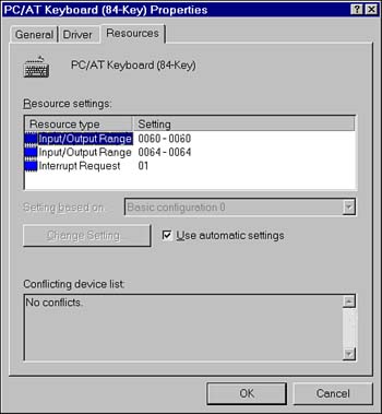
To start communications, the keyboard starts by sending a series of the self-test passed characterAA(hex)to your computer using the wrong parity to indicate that it has not been initialized. When your computer has gone through the boot process sufficiently to be ready to accept data, it sends an error acknowledgment to the keyboardFE(hex). The keyboard responds by correcting the parity and sending the self-test passed character, providing of course it passed its internal self-test. At this point, the keyboard and computer are ready for normal operation. Host InterfaceThe keyboard interface inside your computer is a complete subsystem with its own dedicated microprocessor. The original design used an Intel 8042 microprocessor for handling keyboard communications, but in modern computers, circuitry equivalent to such a microprocessor is typically built in to the chipset. This microprocessor monitors the data and clock lines linking it to the computer, deciphers the serial code, and repackages it in parallel form for passing to your computer. Your computer receives data from the keyboard interface and sends data to it through a pair of I/O ports. When the ports receive a byte and have it ready for processing by your computer, they generate a hardware interrupt. In modern computers, the location of keyboard ports and the interrupt generated by the controller may vary with the hardware design and BIOS of your computer. If you are curious, you can check the ports used from the Windows Control Panel by selecting the Keyboard icon and then the Resources tab. You'll see a display like that shown in Figure 20.5. Figure 20.5. A Windows display of the resources used by the keyboard subsystem.
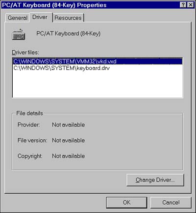
At this point, the keyboard controller passes a scan code sent from the keyboard to your system, and the keyboard BIOS routine determines the character to be sent to your operating system. The standard BIOS interruptprocessing routine generates a second interrupt that permits a subroutine to process the scan code before it gets processed into a character. Under Windows, these BIOS routines are replaced by keyboard drivers that perform the same functions. By default, current consumer versions of Windows install two keyboard driversa real-mode driver (keyboard.drv) and a protected-mode driver (vkd.vxd). You can see the drivers installed in your system or change the drivers using the Drivers tab of the Keyboard Properties dialog box in Windows, as shown in Figure 20.6. Figure 20.6. The Windows display of installed keyboard drivers.
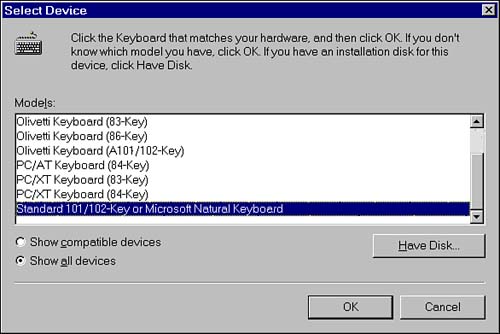
CompatibilityThe vast majority of today's keyboards use the same interfaces, protocols, and scan codes and are essentially interchangeable at the electrical and logical level. Because key layouts often differ, however, your fingers might find some compatibility problems, especially when confronted with the layout of the keys on a new notebook computer. You may encounter compatibility problems in two cases, however. Very old computers and keyboards used a one-way, send-only keyboard design that's different from current designs. Most of these predated the current 101-key design. In the transition period between the acceptance of the two designs, many aftermarket keyboards were switchable between two operating modes. The old, one-way mode was designated XT (or rarely, PC) mode. The modern mode is distinguished as AT (or rarely, PS/2) mode. Very old computers require XT mode keyboards. The connectors used by very old keyboards also differ from the current design, using a large five-pin plug, as discussed later. Note that the connector is not a reliable guide to the operating mode of the keyboard. Keyboards using the large, old, five-pin connector may operate as either XT or AT keyboards. All keyboards using the modern, miniaturized connector operate in the AT mode (although some old models may have switches allowing support of XT mode). Another compatibility issue affects keys beyond the 101 defined for the PS/2 keyboard design. Your computer needs a software driver to recognize these additional keys. Windows generally can identify your keyboard when it scans your hardware and set itself up accordingly with the correct driver (or it will ask you for a disk). If you have reason to believe that its choice was incorrect or if you want to install a keyboard manually into Windows for any reason, Windows gives you that option. You access the keyboard selection in the General tab of the Keyboard Properties dialog box. To open the Keyboard Properties dialog box, select the Keyboard icon in Control Panel. If the keyboard Windows displays is not the one you want, click the Change button. Windows will respond with a list of keyboards it inherently knows how to manage, as shown in Figure 20.7. Figure 20.7. Selecting a keyboard in Windows.
As with installing any hardware on your computer, Windows allows you to install a keyboard without built-in Windows support using a driver supplied by the keyboard-maker. If the keyboard you want to use is not listed as one of those directly supported, click the Have Disk button and slide the floppy disk or CD supplied by your keyboard vendor into the appropriate drive slot when Windows instructs you to. You specify a disk location and complete the installation process as you would with any other hardware device. ConnectionsThe scan-code system and serial signaling simplify the connection scheme used by computer keyboards. Scan codes are sent from the keyboard to the computer serially so that only one wire conductor is needed to convey the keyboard data information. A second conductor is required to serve as a return path for the data signal; as a ground, it serves as a common return for all other circuits in the keyboard cable. To synchronize the logic in the keyboard with that in the computer, a separate wire is used for a keyboard clock signal. A fourth and final wire is used to supply the keyboard with the five-volt direct current power it needs to operate. These four conductors are all that is necessary to link keyboard to computer. The physical embodiment of those signals is the keyboard connector. Nearly all keyboards now use a miniature six-pin DIN connector. This design is usually called PS/2-style because IBM introduced it with its PS/2 computers in 1987, and it has served every since. The six pins are arrayed in a circle around a rectangular plastic tab that, along with three guides in the shield, keys the connector against improper insertion. As with the five-pin connector, the pin numbers follow an irregular pattern. Figure 20.8 shows the six-pin miniature DIN keyboard connector and its signal layout. Figure 20.8. The six-pin miniature DIN keyboard connector.
Only four pins are significant to keyboard use: Pin 1 is assigned keyboard data; pin 3, ground; pin 4, five volts; pin 5, keyboard clock. Pins 2 and 6 are reserved, and the shield is attached as a chassis ground. Table 20.4 lists the signal assignments on the PS/2-style keyboard connector.
Older keyboards use a five-pin pluga standard, as opposed to miniature, DIN connector. Because the five-pin and six-pin keyboard connectors use the same signals with only a slight rearrangement, a simple adapter will convert one style of connector to another. These keyboard adapters are readily available on the computer parts market. If you're so inclined, you can make your own using the interconnection guide given in Table 20.5.
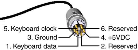
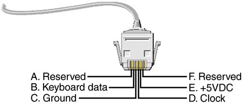
In some computers, the keyboard cable can be disconnected from the keyboard itself. This detachable design makes the cable easy to service (by replacing it) and a single keyboard adaptable between five-pin and six-pin cabling standards. The keyboard-to-cable connection uses a modular (AMP) jack on the rear of the keyboard with a matching plug on the cable, as shown in Figure 20.9. Figure 20.9. The modular keyboard connector and signal assignments.
As shown in the figure, this modular connector has the following signal assignments: A, reserved; B, keyboard data; C, ground; D, keyboard clock; E, five volts; F, reserved. When looking at the gold contacts of the connector, the contacts are labeled in reverse alphabetical order from left to right. Table 20.6 summarizes these signal assignments.
USB PortIn the long run, computer-makers hope to make the keyboard port as obsolete as steam-powered personal computers. The alternative is the Universal Serial Bus (USB), which computer-makers hope will replace all the other ports on the back of your computer. As computers shift to the use of the Universal Serial Bus, keyboard connections will move to this high-speed interface. USB-based keyboards were displayed as early as February, 1996, but the early introduction proved premature. Even in 2003, computer-makers prefer the conventional keyboard interface because it is cheap and reliable, despite admonitions from Intel and Microsoft to move to USB. As the interface matures, however, USB keyboards are destined to become more popular. Because USB is designed and designated a universal interface, one that will link devices other than keyboards, it is treated in a separate chapter devoted to ports, Chapter 10. The inner workings of USB keyboards are immaterial to your computer. It just looks for data packets received through the USB port. Any packets containing keyboard data get routed by the USB driver to the keyboard driver of the operating system. Then the operating system pulls the data from the packets to see what you've typed. If your computer wants to send a command to the keyboard, it notifies the keyboard driver, which generates the code of the command and passes it along to the USB driver, which routes it out the port and to your keyboard as another packet on the USB circuit. The flaw in this design is that it doesn't work until the operating system and its USB drivers load. Before then, the keyboard driver has no route through which to get keystroke codes. That's all right, because if the operating system hasn't loaded, the keyboard driver won't have loaded, either. With neither the USB nor keyboard driver running, your computer faces a problem if it needs to read the keyboard while booting upfor example, to step through the setup menu. Your computer's BIOS makes up for this flaw. It patches together the old and new keyboard systems. |
| [ Team LiB ] |
|