| [ Team LiB ] |
|
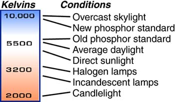
DisplaysYou cannot see data. The information that your computer processes is nothing but ideas, and ideas are intangibleno matter whether in your mind or your computer's. Whereas you can visualize your own ideas, you cannot peer directly into the pulsing digital thought patterns of your computer. You probably have no right to think that you couldif you can't read another person's thoughts, you should hardly expect to read the distinctly nonhuman circuit surges of your computer. The display is your computer's line of communication to you, much as the keyboard enables you to communicate with it. Like even the best of friends, the display doesn't tell you everything, but it does give you a clear picture, one from which you can draw your own conclusions about what the computer is doing. BackgroundAlthough the terms are often used interchangeably, a display and a monitor are distinctly different. A display is the image-producing device itself, the screen that you see. The monitor is a complete box that adds support circuitry to the display. This circuitry converts the signals set by the computer (or some other device, such as a videocassette recorder) into the proper form for the display to use. Although most monitors operate under principles like those of the television set, displays can be made from a variety of technologies, including liquid crystals and the photon-glow of some noble gases. Because of their similar technological foundations, monitors to a great extent resemble the humble old television set. Just as a monitor is a display enhanced with extra circuitry, the television is a monitor with even more signal-conversion electronics. The television incorporates into its design a tuner or demodulator that converts signals broadcast by television stations or a cable television company into about the same form as those signals used by monitors. Beyond the tuner, the television and monitor work in much the same way. Indeed, some old-fashioned computer monitors work as televisions as long as they are supplied the proper signals. New monitors have developed far beyond their television roots, however. They have greater sharpness and purity of color. To achieve these ends, they operate at higher frequencies than television stations can broadcast. Computer displays and monitors use a variety of technologies to create visible images. A basic bifurcation once divided the displays of desktop computers and those of laptop machines. All notebook computers and a growing number of desktop machines use the new technology, the flat-panel display. Most use large liquid crystal displays (LCDs). The remaining desktop computers use monitors based on cathode ray tube (CRT) technology. The old-technology monitors earn their desktop home with low prices, higher resolution, and bigger screens than their LCD counterparts. The glaringly apparent difference between thin LCD panels and fat cathode ray tubes hides far greater internal dissimilarities. About the only characteristic the two technologies share is that they make images. CRTs and LCDs differ not only in how they form images but also how they are viewed and how they are best connected to your computer. Cathode Ray TechnologyThe oldest electronic image-generating system still in use is the cathode ray tube. The name is purely descriptive. The device is based on a special form of vacuum tubea glass bottle that is partially evacuated and filled with an inert gas at very low pressure. The tube of the CRT is hardly a tube but more flask-shaped, with a thin neck that broadens like a funnel into a wide, nearly flat face. Although CRTs appear to be made like simple bottlesin fact, people in the monitor business sometimes refer to CRTs as bottlestheir construction is surprisingly complex and involves a variety of glasses of many thicknesses. The face of the typical CRT, for example, often is about an inch thick. The cathode in the CRT name is a scientific term for a negatively charged electrode. In a CRT, a specially designed cathode shoots a beam or ray of electrons toward a positively charged electrode, the anode. (Electrons, having a negative charge, are naturally attracted to positive potentials.) Because it works like a howitzer for electrons, the cathode of a CRT is often called an electron gun. The electrons race on their way at a substantial fraction of the speed of light, driven by the high-voltage potential difference between the cathode and anode, sometimes as much as 25,000 volts. At the end of their flight to the anode, the electrons crash into a layer of a coating made from phosphor compounds that has the wondrous property of converting the kinetic energy of the electrons into visible light. Physical CharacteristicsThe CRT is a physical entity that you can hold in your hand, drop on the floor, and watch shatter. Little of its design is by chancenearly every design choice in making the CRT has an effect on the image you see. Four elements of the CRT exert the greatest influence on the kind and quality of image made by a monitor. The phosphors chosen for the tube affect the color and persistence of the display. The electron guns actually paint the image, and how well they work is a major factor in determining image sharpness. In color CRTs, the shadow mask or aperture grille limits the ultimate resolution of the screen. The face of the screen and the glare reflected from it affect both image contrast and how happy you will be in working with a monitor. PhosphorsAt the end of the electrons' short flight, from the gun in the neck of a CRT to the inside of its wide, flat face, lies a layer of a phosphor-based compound with a wonderful propertyit glows when struck by an electron beam. The image you see in a CRT is the glow of the electrically stimulated phosphor compounds, simply termed phosphors in the industry. Not all the phosphorous compounds used in CRTs are the same. Different compounds and mixtures glow in various colors and for various lengths of time after being struck by the electron beam. The type of phosphor determines the color of the image on the screen. Several varieties of amber, green, and whitish phosphors are commonly used in monochrome displays. Color CRT displays use three different phosphors painted in fine patterns across the inner surface of the tube. The patterns are made from dots or stripes of the three additive primary colorsred, green, and bluearrayed next to one another. A group of three dots is called a color triad or color triplet. One triad of dots makes up what's called a picture element, often abbreviated as pixel (although some manufacturers prefer to shorten picture element to pel). The makers of color monitors individually can choose each of the three colors used in forming the color triads on the screen. Most monitor-makers have adopted the same phosphor family, which is called P22 (or B22, which is the same thing with a different nomenclature), so the basic color capabilities of most multihued monitors are the same. The color monitor screen can be illuminated in any of its three primary colors by individually hitting the phosphor dots associated with that color with the electron beam. Other colors can be made by illuminating combinations of the primary colors. By varying the intensity of each primary color, the tube can display a nearly infinite spectrum. Monochrome displays have their CRTs evenly coated with a single, homogenous phosphor so that wherever the electron beam strikes, the tube glows in the same color. The color of the phosphors determines the overall color that the screen glows. Just as important to screen readability as the phosphor colors is the background color of the display tube. The background area on a color screenthat is, the space in between the phosphor dotsis called the matrix. It is never illuminated by the electron beam. The color of the matrix determines the color screen's background color (usually termed matrix color)what it looks like when the power is off, either pale gray, dark green-gray, or nearly black. Darker and black matrixes give an impression of higher contrast to the displayed images. Lighter-gray matrixes make for purer whites. The distinctions are subtle, however, and unless you put two tubes side-by-side, you're unlikely to appreciate the difference. Color TemperatureIf your work involves critical color matching, the color temperature of your monitor can be an important issue. White light is not white, of course, but a mixture of all colors. Alas, all whites are not the same. Some are richer in blue, some in yellow. The different colors of white are described in their color temperature, the number of kelvins (degrees Celsius above absolute zero) that a perfect luminescent body would need to be to emit that color. Like the incandescence of a hot iron horseshoe in the blacksmith's forge, as its temperature gets higher the hue of a glowing object shifts from red to orange to yellow and on to blue-white. Color temperature simply assigns an absolute temperature rating to these colors. Figure 24.1 shows the effect of color temperature. Figure 24.1. The color temperatures associated with various conditions.
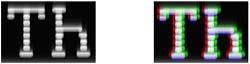
For example, ordinary light bulbs range from 2,700 to 3,400 kelvins. Most fluorescent lights have noncontinuous color spectra rich in certain hues (notably green) while lacking others, which makes assigning a True Color temperature impossible. Other fluorescent lamps are designed to approximate daylight with color temperatures of about 5,000 kelvins. Monitors are designed to glow with the approximate color temperature of daylight rather than incandescent or fluorescent light. Unfortunately, not everyone has the same definition of daylight. Noonday sun, for instance, ranges from 5,500 to 6,000 kelvins. Overcast days may achieve a color temperature of 10,000 kelvins because the scattered blue glow of the sky (higher color temperature) dominates the yellowish radiation from the sun. The colors and blend of the phosphors used to make the picture tube screen and the relative strengths of the electron beams illuminating those phosphors determine the color temperature of a monitor. Some engineers believe the perfect day is a soggy, overcast afternoon suited only to ducks and Englishmen and opt to run their monitors with a color temperatures as high as 10,000 kelvins. Others, however, live in a Kodachrome world where the color temperature is the same 5,300 kelvins as a spring day with tulips in the park. Many monitors now add color temperature to their setup menus, so you can choose whether you want 5000-kelvin or 8500-kelvin whiteor something else entirely. Unless you have a need to make precise color matches, the temperature setting you use is only a matter of personal preference. Electron GunsTo generate the beams that light the phosphors on the screen, a CRT uses one or more electron guns. An electron gun is an electron emitter (a cathode) in an assembly that draws the electrons into a sharp, high-speed beam. To move the beam across the breadth of the tube face (so that the beam doesn't light just a tiny dot in the center of the screen), a group of powerful electromagnets arranged around the tube, called the yoke, bend the electron beam in the course of its flight. The magnetic field set up by the yoke is carefully controlled and causes the beam to sweep each individual display line down the face of the tube. Monochrome CRTs have a single electron gun that continuously sweeps across the screen. Most color tubes have three guns, although some color televisions and monitors boast "one-gun" tubes, which more correctly might be called "three guns in one." The gun count depends on the definition of a gun. Like all color CRTs, the one-gun tubes have three distinct electron-emitting cathodes that can be individually controlled. The three cathodes are fabricated into a single assembly that allows them to be controlled as if they were generating only a single beam. In a three-gun tube, the trio of guns is arranged in a triangle. So-called "one-gun" tubes arrange their cathodes in a straight line, often earning the epithet inline guns. In theory, inline guns should be easier to set up, but as a practical matter, excellent performance can be derived from either arrangement. The three guns in a color CRT emit their electrons simultaneously, and the three resulting beams are steered together by force of a group of electromagnets around the neck of the tube called the yoke. Monitors provide individual adjustments, both mechanical and electrical, for each of the three beams to ensure that each beam falls exactly on the same triplet of color dots on the screen as the others. Because these controls help the three beams converge on the same triad, they are called convergence controls. The process of adjusting them is usually termed color alignment. ConvergenceThe three electron beams inside any color monitor must converge on exactly the right point on the screen to illuminate a single triad of phosphor dots. If a monitor is not adjusted properlyor if it is not designed or made properlythe three beams cannot converge properly to one point. Poor convergence results in images with rainbow-like shadows and a loss of sharpness and detail. Individual text characters no longer appear sharply defined but become two- or three-color blurs. Monochrome monitors are inherently free from such convergence problems because they have but one electron beam. Figure 24.2 shows the difference between good and poor convergence. Figure 24.2. Excellent (left) and poor convergence on a monitor screen.
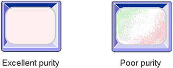
Convergence problems are a symptom rather than a cause of monitor deficiencies. Convergence problems arise not only from the design of the display but also from the construction and setup of each individual monitor. It can vary widely from one display to the next and may be aggravated by damage during shipping. The result of convergence problems is most noticeable at the screen periphery because that's where the electron beams are the most difficult to control. When bad, convergence problems can be the primary limit on the sharpness of a given display, having a greater negative effect than wide dot-pitch or low bandwidth (discussed later). Many monitor-makers claim that their convergence is a given fraction of a millimeter at a particular place on the screen. If a figure is given for more than one screen location, the center of the screen invariably has a lower figuretighter, better convergencethan a corner of the screen. The number given is how far one color may spread from another at that location. Lower numbers are better. Typical monitors may claim convergence of about 0.5 (one-half) millimeter at one of the corners of the screen. That figure often rises 50 percent higher than the dot-pitch of the tube, making the convergence the limit on sharpness for that particular monitor. Misconvergence problems often can be corrected by adjustment of the monitor, usually using the monitor's internal convergence controls. A few, high-resolution (and high-cost) monitors even have external convergence adjustments. But adjusting monitor convergence is a job for the specialistand that means getting a monitor converged can be expensive, as is any computer service call. Many monitor-makers now claim that their products are converged for life. Although this strategy should eliminate the need to adjust them, it also makes it mandatory to test your display before you buy it. You don't want a display that's been badly converged for life. PurityThe ability of a monitor to show you an evenly lit screen that does not vary in color across its width is termed purity. A monitor with good purity will be able to display a pure white screen without a hint of color appearing. A monitor with poor purity will be tinged with one color or another in large patches. Figure 24.3 illustrates the screens with good and poor purity. Figure 24.3. Comparison of good and bad monitor purity.
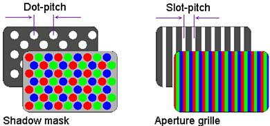
Poor purity often results from the shadow mask or aperture grille of a cathode ray tube becoming magnetized. Degaussing the screen usually cures the problem. Most larger monitors have built-in automatic degaussers. You can degauss your monitor with a degaussing loop designed for color televisions or even a bulk tape eraser. Energize the degaussing coil or tape eraser in close proximity to the screen, then gradually remove the coil to a distance of three or more feet away before switching it off. The gradually declining alternating magnetic field will overpower the static field on the mask, and the gradual removal of the alternating field prevents the strong field from establishing itself on the mask. Shadow MasksJust pointing the electron beams at the right dots is not enough, because part of the beam can spill over and hit the other dots in the triplet. The result of this spillover is a loss of color puritybright hues become muddied. To prevent this effect and make images as sharp and colorful as possible, most color CRTs used in computer displays and televisions alike have a shadow maska metal sheet with fine perforations in itlocated inside the display tube and a small distance behind the phosphor coating of the screen. The shadow mask and the phosphor dot coating on the CRT screen are critically arranged so that the electron beam can only hit phosphor dots of one color. The other two colors of dots are in the "shadow" of the mask and cannot be seen by the electron beam. The spacing of the holes in the shadow mask to a great degree determines the quality of the displayed image. For the geometry of the system to work, the phosphor dots on the CRT screen must be spaced at the same distance as the holes in the mask. Because the hole spacing determines the dot spacing, it is often termed the dot-pitch of the CRT. The dot-pitch of a CRT is simply a measurement of the distance between dots of the same color. It is an absolute measurement, independent of the size of the tube or the size of the displayed image. The shadow mask affects the brightness of a monitor's image in two ways. The size of the holes in the mask limits the size of the electron beam getting through to the phosphors. Off-axis from the gunsthat is, toward the corners of the screenthe round holes appear oval to the gun and less of the beam can get through. As a result, the corners of a shadow mask screen are often dimmer than the center, although the brightness difference may not be distinguishable. The mask also limits how high the electron beam intensity can be in a given CRT. A stronger beamwhich makes a brighter imageholds more energy. When the beam strikes the mask, part of that energy is absorbed by the mask and becomes heat, which raises the temperature of the mask. In turn, this temperature rise makes the mask expand unpredictably, distorting it minutely and blurring the image. To minimize this heat-induced blur, monitor-makers are moving toward making shadow masks from materials that have a low coefficient of thermal expansion. That is, they change size as little as possible with temperature. The alloy Invar is favored for shadow masks because of its capability to maintain a nearly constant size as it warms. Aperture GrillesWith all the problems associated with shadow masks, you might expect someone to come up with a better idea. Sony Corporation did exactly that, inventing the Trinitron picture tube. The Trinitron uses an aperture grilleslots between a vertical array of wiresinstead of a mask. The phosphors are painted on the inner face of the tube as interleaved stripes of the three additive primary colors. The grille blocks the electron beam from the wrong stripes, just as a shadow-mask blocks it from the wrong dots. The distance between two sequential stripes of the same color is governed by the spacing of the slots between the wiresthe slot-pitch of the tube. Because the electron beam fans out as it travels away from the electron gun and because stripes are farther from the gun than is the mask, the stripes are spaced a bit farther apart than the slot-pitch. Their spacing is termed screen-pitch. For example, a 0.25-millimeter slot-pitch Trinitron might have a screen-pitch of 0.26 millimeters. Figure 24.4 shows how dot-pitch and slot-pitch are measured. Figure 24.4. Measuring dot-pitch and slot-pitch.
The wires of the aperture grille are quite thick, about two-thirds the width of the slot-pitch. For example, in a Trinitron with a 0.25-millimeter slot-pitch, the grille wires measure about 0.18 millimeters in diameter because each electron beam is supposed to illuminate only one-third of the screen. The wires shadow the other two-thirds from the beam to maintain the purity of the color. The aperture grille wires are held taut, but they can vibrate. Consequently, Trinitron monitors have one or two thin tensioning wires running horizontally across the screen. Although quite fine, these wires cast a shadow on the screen that is most apparent on light-colored screen backgrounds. Some people find the tensioning wire shadows objectionable, so you should look closely at a Trinitron before buying. Trinitrons hold a theoretical brightness advantage over shadow-mask tubes. Because the slots allow more electrons to pass through to the screen than do the tiny holes of a shadow mask, a Trinitron can (in theory) create a brighter image. This added brightness is not borne out in practice. However, Trinitrons do excel in keeping their screens uniformly bright. The aperture grille wires of a Trinitron block the beam only in one dimension, and they don't impinge as much on the electron beam at the screen edges. Required Dot-PitchRegardless of whether a monitor uses a shadow mask with a dot-pitch or an aperture grille with a slot-pitch, the spacing of image triads on the screen is an important constituent in monitor quality. A monitor simply cannot put dots any closer together than the holes in the mask or grille allow. It's easy to compute the pitch necessary for a resolution level in a computer system. Just divide the screen size by the number of dots required to be displayed. For example, a typical small display measures 14 inches diagonally. A horizontal line stretching across the full width of such a screen would measure 11.2 inches or about 285 millimeters. To properly display an SVGA image (800 pixels by 600 pixels) would require a dot-pitch of 0.36 millimeters or smaller (that is, 285/800 of a millimeter or less). Often a monitor's image is somewhat smaller than full screen width and such displays require an even finer dot-pitch. The larger the display, the coarser the dot-pitch can be for a given level of resolution. Line WidthAnother factor limits the sharpness of monitor images: the width of the lines drawn on the screen. Ideally, any vertical or horizontal line on the screen will appear exactly one pixel wide, but in practical monitors, the width of a line may not be so compliant. If lines are narrower than one pixel wide, thin black lines will separate adjacent white lines and wide white areas will be thinly striped in black. If the line width exceeds the size of a pixel, the display's ability to render fine detail will be lost. The ideal line width for a monitor varies with the size of the screen and the resolution displayed on the screen. As resolution increases, lines must be narrower. As screen size goes up (with the resolution constant), line width must increase commensurately. You can calculate the required line width the same way as for the preceding dot-pitch example. The line width should equal the maximum dot-pitch you calculate. In other words, for the preceding 14-inch screen at SVGA resolution, you'd want a line width of 0.36 millimeters. Several factors influence the width of lines on the screen. The monitor must be able to focus its electron beam into a line of ideal width. However, width also varies with the brightness of the beambrighter beams naturally tend to expand out of focus. Consequently, when you increase the brightness of your monitor, the sharpness of the image may decline. For this reason, test laboratories usually make monitor measurements at a standardized brightness level. Screen CurvatureMost CRTs have a distinctive shape. At one end, a narrow neck contains the electron gun or guns. Around the neck fits the deflection yoke, an external assembly that generates the magnetic fields that bend the electron beams to sweep across the inner surface of the wide face of the tube. The tube emerges from the yoke as a funnel-like flaring, which enlarges to the rectangular face of the screen itself. This face often (but becoming much less common) is a spherically curving surface. The spherical curve of the face makes sense for a couple of reasons. It makes the distance traveled by the electron beam more consistent at various points on the screen, edge to center to edge. A truly flat screen would require the beam to travel farther at the edges than at the center and would require the beam to strike the face of the screen obliquely, resulting in image distortion. Although this distortion can be compensated for electrically, the curving screen helps things along. In addition, the CRT is partly evacuated, so normal atmospheric pressure is constantly trying to crush the tube. The spherical surface helps distribute this potentially destructive force more evenly, making the tube stronger. Screen curvature has a negative side effect. Straight lines on the screen appear straight only from one observation point. Move your head closer, farther away, or to one side, and the supposedly straight lines of your graphic images will bow this way and that. Technology has made the reasons underlying spherical curved screens less than compelling. The geometry of inline guns simplifies tube construction and alignment sufficiently that cylindrically curved screens are feasible. They have fewer curvilinear problems because they warp only one axis of the image. Trinitrons characteristically have faces with cylindrical curves. Most shadow-mask tubes have spherical faces. In the last few years, the technical obstacles to making genuinely flat screens have been surmounted. Besides the easier geometry offered by true flat-screen CRTs, they bring another benefit. The curved screen on conventional tubes reflects light from nearly the entire area in front of the tube. No matter where you point the display, it's sure to pick up some glare. True flat-screen tubes reflect glare over a very narrow angle. If you point a flat-screen display slightly downward, most of the room glare will reflect down onto your keyboard and away from your eyes. Resolution Versus AddressabilityThe resolution of a video system refers to the fineness of detail that it can display. It is a direct consequence of the number of individual dots that make up the screen image and is therefore a function of both the screen size and the dot-pitch. Because the size and number of dots limit the image quality, the apparent sharpness of screen images can be described by the number of dots that can be displayed horizontally and vertically across the screen. For example, the resolution required by the Video Graphics Array system in its standard graphics mode is 640 dots horizontally by 480 vertically. Modern display systems may produce images with as many as 1600x1200 dots in their highest resolution mode. Sometimes, however, the resolution available on the screen and that made by a computer's display adapter are not the same. For example, a video mode designed for the resolution capabilities of a color television set hardly taps the quality available from a computer monitor. On the other hand, the computer-generated graphics may be designed for a display system that's sharper than the one being used. You might, for instance, try to use a television in lieu of a more expensive monitor. The sharpness you actually see would then be less than what the resolution of the video system would have you believe. Resolution is a physical quality of the video display systemthe monitorthat's actually being used. It sets the ultimate upper limit on the display quality. In color systems, the chief limit on resolution is purely physicalthe convergence of the system and the dot-pitch of the tube. In monochrome systems, which have no quality-limiting shadow masks, the resolution is limited by the bandwidth of the monitor, the highest frequency signal with which it can deal. (Finer details pack more information into the signals sent from computer system to monitor. The more information in a given time, the higher the frequency of the signal.) Addressability is essentially a bandwidth measurement for color monitors. It indicates how many different dots on the screen the monitor can point its electron guns at. It ignores, however, the physical limit imposed by the shadow mask. In other words, addressability describes the highest quality signals the monitor can handle, but the full quality of those signals is not necessarily visible to you onscreen. Anti-Glare TreatmentMost mirrors are made from glass, and glass tries to mimic the mirror whenever it can. Because of the difference between the index of refraction of air and that of glass, glass is naturally reflective. If you make mirrors, that's great. If you make monitorsor worse yet, use themthe reflectivity of glass can be a big headache. A reflection of a room light or window from the glass face of the CRT can easily be brighter than the glow of phosphors inside. As a result, the text or graphics on the display tend to "wash out" or be obscured by the brightness. The greater the curvature of a monitor screen, the more apt it is to have a problem with reflections. You can't change the curve of your monitor's face, but anti-glare treatments can reduce or eliminate reflections from the monitor face. Several glare-reduction technologies are available, and each varies somewhat in its effectiveness. MeshThe lowest tech and least expensive anti-glare treatment is simply a fabric mesh, usually nylon. The mesh can either be placed directly atop the face of the screen or in a removable frame that fits about half an inch in front of the screen. Each hole in the mesh acts like a short tube, allowing you to see straight in at the tube, but cutting off light from the sides of the tube. Your straight-on vision gets through unimpeded, while glare that angles in doesn't make it to the screen. As simple as this technique is, it works amazingly well. The least expensive after-market anti-glare system uses mesh suspiciously similar to pantyhose stretched across a frame. Unfortunately, this mesh has an unwanted side effect. Besides blocking the glare, it also blocks some of the light from the screen and makes the image appear darker. You may have to turn the brightness control up to compensate, which may make the image bloom and lose sharpness. MechanicalGlare can be reduced by mechanical meansnot by a machine that automatically intercepts glare before it reaches the screen, but by mechanical preparation of the screen surface. By lightly grinding the glass on the front of the CRT, the face of the screen can be made to scatter rather than reflect light. Each rough spot on the screen that results from the mechanical grinding process reflects light randomly, sending it every which direction. A smooth screen reflects a patch of light all together, like a mirror, reflecting any bright light source into your eyes. Because the light scattered by the ground glass is dispersed, less of it reaches your eyes and the glare is not as bright. However, because the coarse screen surface disperses the light coming from inside the tube as well as that reflected from the tube face, it also lessens the sharpness of the image. The mechanical treatment makes text appear slightly fuzzier and out of focus, which to some manufacturers is a worse problem than glare. CoatingEngineers can reduce the glare reflected from a CRT screen by applying a coating with dispersive or interference properties to the screen. A dispersive coating forms a rough film on the face of the CRT. This rough surface acts in the same way as a ground-glass screen would, scattering light that would otherwise reflect back as glare. An optical interference coating cancels out reflections. Interference coatings work by reflecting light between multiple thin layers of a compound, such as magnesium fluoride. By precisely controlling the thickness of this coating, light can be made to reflect in such a way its waves cancel out. The fluoride coating is made to be a quarter the wavelength of light (usually of light at the middle of the spectrum). Light going through the fluoride and reflecting from the screen thus emerges from the coating out of phase with the light striking the fluoride surface, visually canceling out the glare. Multiple layers are tuned to the different frequencies of the colors of visible light. Camera lenses are coated to achieve exactly the same purpose, the elimination of reflections. A proper interference coating can minimize glare without affecting image sharpness or brightness. PolarizationLight can be polarizedthat is, its photons can be restricted to a single plane of oscillation. A polarizing filter allows light of only one polarization to pass. Two polarizing filters in a row can be arranged to allow light of only one plane of polarization to pass (by making the planes of polarization of the filters parallel), or the two filters can stop light entirely when their planes of polarization are perpendicular. The first filter lets only one kind of light pass; the second filter lets only another kind of light pass. Because none of the second kind of light reaches the second filter, no light gets by. When light is reflected from a surface, its polarization is shifted by 90 degrees. This physical principle makes polarizing filters excellent reducers of glare. A sheet of polarizing material is merely placed a short space in front of a display screen. Light from a potential source of glare goes through the screen and is polarized. When it strikes the display and is reflected, its polarization is shifted 90 degrees. When it again reaches the filter, it is out of phase with the filter and cannot get through. Light from the display, however, only needs to go through the filter once. Although this glow is polarized, there is no second screen to impede its flow to your eyes. Every anti-glare treatment has its disadvantage. Mesh makes an otherwise sharp screen look fuzzy, because smooth characters are broken up by the cell structure of the mesh. Mechanical treatments are expensive and tend to make the screen appear to be slightly fuzzy or out of focus. The same is true of coatings that rely on the dispersion principle. Optical coatings, polarizing filters, and even mesh suffer from their own reflections. The anti-glare material itself may add its own bit of glare. In addition, all anti-glare treatmentspolarizing filters in particulartend to make displays dimmer. The polarizing filter actually reduces the brightness of a display to one-quarter its untreated value. Even with their shortcomings, however, anti-glare treatments are amazingly effective. They can ease eyestrain and eliminate the headaches that come with extended computer use. Deflection AngleAnother difference between CRTs is their deflection angle, which measures the maximum degree the tube allows its electron beam to bend. This corresponds to the angle at which the tube flares out. A tube with a narrow deflection angle will be long with a small screen. A wide deflection angle permits large screens with shorter tubes. Ideally, the best tube would be the shortest, but as the deflection angle increases, it becomes more difficult to control the electron beam and make a perfect image. Consequently, lower deflection angles usually produce better images. Improved technology has allowed deflection angles to increase while maintaining image quality. This allows monitors to be shorter and take up less desk space. A monitor can deflect the electron beam inside its CRT both left and right of the center-line path the beam would take without deflection. By custom, the deflection angle listed for a given CRT is the total deflection from maximum left to maximum right. Until the late 1990s, nearly all computer monitors used CRTs with deflection angles of 90 degrees. Television sets, which can get by with less image quality, typically use 110-degree tubes. In 1999, computer monitors with 100-degree tubes began to enter the market. Image CharacteristicsThe electronics of a monitor control the size, shape, and other aspects of the image displayed on a monitor's screen. The image qualities are defined and characterized in a number of ways. The most rudimentary is screen sizethe bigger your monitor screen, the larger the images it can make. Because of the underscanning common among computer monitors, however, the actual image size is almost always smaller than the screen. The aspect ratio of the image describes its shape independent of its size. Most monitors give you a variety of controls to alter the size and shape of the image, so you are the final arbiter of what things look like on your monitor screen. Screen SizeThe most significant measurement of a CRT-based monitor is the size of its screen. Although seemingly straightforward, screen size has been at best an ambiguous measurement and at worst downright misleading. The confusion all started with television, where confusion often begins. The very first television sets had round CRTs, and their size was easy to measuresimply the diameter of the tube. When rectangular tubes became prevalent in the 1950s, the measurement shifted to the diagonal of the face of the tube. The diagonal was, of course, the closest equivalent to the diameter of an equivalent round tube. It was also the largest dimension that a television manufacturer could reasonably quote. Unlike television images, which usually cover the entire face of the CRT, computer monitors limit their images to somewhat less. The image is most difficult to control at the edges of the screen, so monitor-makers maintain higher quality by restricting the size of the image. They mask off the far edges of the CRT with the bezel of the monitor case. That bezel means that no image can fill the entire screenat least no image that you can entirely see. The tube size becomes irrelevant to a realistic appraisal of the image. Some monitor-makers persisted in using it to describe their products. Fortunately most of the industry recognized this measuring system as optimistic exaggeration and began using more realistic diagonal measurement of the actual maximum displayable image area. VESA adopted the diagonal of the maximum image area as the measurement standard in its Video Image Area Definition standard, version 1.1, which it published on October 26, 1995. This standard requires that the screen image area be given as horizontal and vertical measurements of the actual active image area when the monitor is set up by the manufacturer using the manufacturer's test signals. The dimensions must be given in millimeters, with an assumed maximum variance of error of plus or minus two percent. Wider tolerances are allowed but must be explicitly stated by the manufacturer. In no case can the expressed image dimensions exceed the area visible through the monitor bezel. Because the aspect ratio of computer monitor displays is 4:3, computation of the horizontal and vertical screen dimensions from the diagonal is easy. The diagonal represents the hypotenuse of a 3-4-5 right triangle, and that ratio applies to all screen sizes. Table 24.2 lists the dimensions for the most common nominal screen sizes.
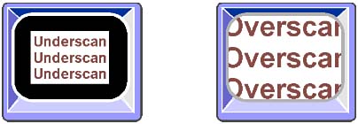
Portrait displays, which are designed to give you a view more like the printed sheets that roll out of your laser printer and into envelopes, merely take an ordinary CRT and turn it on its side. The market is not large enough to justify development of custom CRTs for portrait applications. Moreover, the 4:3 aspect ratio works fine because the "active" image on a sheet of letterheadthe space actually occupied by printing once you slice off the top, bottom, left, and right marginsis about eight by ten inches, a nearly perfect fit on a standard picture tube. When measuring the images on these portrait displays, horizontal becomes vertical, and all measurements rotate 90 degrees. Overscan and UnderscanTwo monitors with the same-size screens may have entirely different onscreen image sizes. Composite monitors are often afflicted by overscanthey attempt to generate images larger than their screen size, and the edges and corners of the active display area may be cut off. (The overscan is often designed in so that as the components inside the monitor age and become weaker, the picture shrinks down to normal sizelikely over a period of years.) Underscan is the opposite conditionthe image is smaller than nominal screen size. For a given screen size, an overscanned image will appear larger at the expense of clipping off the corners and edges of the image as well as increasing distortion at the periphery of the image. Underscanning wastes some of the active area of the monitor screen. Figure 24.5 illustrates the effects of underscanning and overscanning on the same size screen. Figure 24.5. Underscan and overscan compared.
Underscan is perfectly normal on computer displays and does not necessarily indicate any underlying problems unless it is severefor example, when it leaves a two-inch black band encircling the image. Underscanning helps keep quality high because image geometry is easier to control nearer to the center of the screen than it is at the edges. Pulling in the reigns on the image can ensure that straight lines actually are displayed straight. Moreover, if you extend the active image to the very edge of the bezel and you change your viewing position so that you are not facing the screen straight on, the edge of the image may get hidden behind the bezel. The glass in the face of the screen is thicker than you might think, on the order of an inch (25 millimeters), enough that the third dimension will interfere with your most careful alignment. On the other hand, whereas overscan gives you a larger image and is the common display mode for video systems, it is not a good idea for computer monitor images. Vital parts of the image may be lost behind the bezel. You may lose the first character or two from each line of type of one edge of a drafting display to overscan. With video, however, people prefer to see as big an image as possible and usually pay little attention to what goes on at the periphery. Broadcasters, in fact, restrict the important part of the images they deal with to a "safe area" that will be completely viewable, even on televisions with substantial overscan. Aspect RatioThe relationship between the width and height of a monitor screen is termed its aspect ratio. Today, the shape of the screen of nearly every monitor is standardized, as is that of the underlying CRT that makes the image. The screen is 1.33 times wider than it is high, resulting in the same 4:3 aspect ratio used in television and motion pictures before the wide-screen phenomenon took over. Modern engineers now prefer to put the vertical number first to produce aspect ratios that are less than one. Expressed in this way, video has a 3:4 aspect ratio, a value of 0.75. The choice of aspect ratio is arbitrary and a matter of aesthetics. According to classical Greek aesthetics, the Golden Ratio with a value of about 0.618 is the most beautiful. The exact value of the Golden Ratio is irrational, (SQRT(5)-1)/2. Its beauty is mathematical as well as aesthetic, the solution to the neat little equation x+1 = 1/x. (Hardly coincidental, expressed as a ratio of horizontal to vertical, the Golden Ratio becomes 1.618, the solution to x-1 = 1/x.) Various display systems feature their own aspect ratios. The modern tendency is toward wider aspect ratios. For example, High Definition Television (HDTV) stretches its aspect ratio from the 3:4 of normal video and television to 9:16. The normal negatives you make with your 35 mm camera have a 4:6 aspect ratio. (These numbers are often reversedfor example, 16:9 for HDTVbut they refer to the same screen shape, which has a longer horizontal axis than vertical axis.) The reason video is so nearly square carries over from the early days of television when cathode ray tubes had circular faces. The squarer the image, the more of the circular screen was put to use. Figure 24.6 compares the aspect ratios of three common display systems. Figure 24.6. Aspect ratios of display systems.
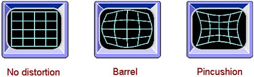
The image on your monitor screen need not have the same aspect ratio as the tube, however. The electronics of monitors separate the circuitry that generates the horizontal and vertical scanning signals and results in their independent control. As a result, the relationship between the two can be adjusted, and that adjustment results in an alteration of the aspect ratio of the actual displayed image. For example, by increasing the amplification of the horizontal signal, the width of the image is stretched, thus raising the aspect ratio. Image SizingNormally you set up your monitor to display the best possible image at the resolution you use most often. Most people leave their monitors locked at one resolution level. Those who change resolution settings often run into a problemthe monitor produces different size images at different resolution levels. Images with more dots are larger than those with fewer. Monitor-makers developed autosizing technology to compensate for changes in resolution. Autosizing works by examining the video signal and automatically adjusting the monitor to compensate for different line widths and screen heights. True autosizing works regardless of the signal going to the monitor and scales the image to match the number of display lines. Image DistortionBetween the electron guns and the phosphors in a cathode ray tube, the electron beam passes through an electronic lens and deflection system that focuses and steers the beam to ensure that its path across the screen is the proper size and in the proper place. The electronics of the monitor control the lens and deflection system, adjusting it throughout the sweep of the electron beam across the screen. In addition to other chores, the electronics must compensate for the difference in the path of the electron beam at different screen positions. Modern monitors do a magnificent job of controlling beam placement. When the control system is not properly adjusted, however, the image may exhibit any of a number of defects. Because these defects distort the image from its desired form, they are collectively called image distortion. The two most common forms of image distortion are barrel distortion and pincushion distortion. Barrel distortion causes vertical or horizontal lines in the image to bow outward so that the center of the lines lies closer to the nearest parallel edge of the screen. Pincushion distortion causes the vertical or horizontal lines in the image to bow inward so that the center of the lines is closer to the center of the screen. Figure 24.7 shows these two kinds of image distortion. Figure 24.7. Barrel and pincushion distortion.
Barrel and pincushion distortion arise from the same causeimproper image compensationand are essentially opposites of one another. Overcompensate for pincushion distortion and you get barrel distortion. Collectively, the two are sometimes simply called pincushioning, no matter which way the lines bow. Pincushioning is always worse closer the edges of the image. All monitors have adjustments to compensate for pincushioning, although these adjustments are not always available to you. They may be hidden inside the monitor. Other monitors may include pincushioning adjustments in their control menus. Technicians usually use test patterns that display a regular grid on the screen to adjust monitors to minimize pincushioning. You can usually use a full-screen image to adjust the pincushioning controls so that the edges of the desktop background color are parallel with the bezel of your monitor. Less common is trapezoidal distortion, which leaves lines at the outer edge of the screen straight but not parallel to the bezel. In other words, instead of your desktop being a rectangle, it is a trapezoid with one side shorter than its opposite side. As with pincushioning, all monitors have controls for trapezoidal distortion but not all make them available to you as the user of the monitor. If your monitor does have an external control for trapezoidal distortion, you adjust it as you do for pincushioning. Image ControlsA few monitors (far from a majority) make coping with underscan, overscan, and odd aspect ratios simply a matter of twisting controls. These displays feature horizontal and vertical size (or gain) controls that enable you to adjust the size and shape of the image to suit your own tastes. With these controlsproviding they have adequate rangeyou can make the active image touch the top, bottom, and sides of the screen bezel, or you can shrink the bright area of your display to a tiny (but geometrically perfect) patch in the center of your screen. Size and position controls give you command of how much screen the image on your monitor fills. With full-range controls, you can expand the image to fill the screen from corner to corner or reduce it to a smaller size that minimizes the inevitable geometric distortion that occurs near the edges of the tube. A full complement of controls includes one each of the following: horizontal position (sometimes termed phase), vertical position, horizontal size (sometimes called width), and vertical size (or height). A wide control range is better than a narrow one. Some monitors skimp on one or more controls and limit you in how large you can make the onscreen image. Worse, sometimes a monitor-maker doesn't include a control at all. For example, some monitors have no horizontal size controls. As a result, you cannot adjust both the size and aspect ratio of the image. The optimum position for these controls is on the front panel, where you can adjust them and view the image at the same time. Controls on the rear panel require you to have gorilla-like arms to reach around the monitor to make adjustments while checking their effect. Image controls come in two types: analog and digital. Analog controls are the familiar old knobs like you find on vintage television sets. Twist one way and the image gets bigger; twist the other and it shrinks. Analog controls have one virtuejust by looking at the knob you know where they are set, whether at one or the other extreme of their travel. The control itself is a simple memory system; it stays put until you move it again. Analog controls, however, become dirty and wear out with age, and they usually enable you to set just one value per knobone value that must cover all the monitor's operating modes. Digital controls give you pushbutton control over image parameters. Press one button, and the image gets larger or moves to the left. Another compensates in the opposite direction. Usually digital controls are linked with a microprocessor, memory, and mode-sensing circuitry so that you can preset different image heights and widths for every video standard your monitor can display. Digital controls don't get noisy with age and are more reliable and repeatable, but you never know when you are approaching the limit of their travel. Most have two-speed operationhold them in momentarily and they make minute changes; keep holding them down and they shift gears to make gross changes. Of course, if you don't anticipate the shift, you'll overshoot the setting you want and spend a few extra moments zeroing in on the exact setting. Most CRT-based displays also carry over several controls from their television progenitors. Nearly every computer monitor has a brightness control, which adjusts the level of the scanning electron beam; this in turn makes the onscreen image glow brighter or dimmer. The contrast control adjusts the linearity of the relationship between the incoming signal and the onscreen image brightness. In other words, it controls the brightness relationship that results from different signal levelshow much brighter high-intensity is. In a few displays, both the brightness and contrast functions are combined into a single "picture" control. Although a godsend to those who might get confused by having to twiddle two knobs, the combined control also limits your flexibility in adjusting the image to best suit your liking. Flat-Panel Display TechnologyThroughout the age of television, predictions of the future have almost universally included big, flat TV screens. Almost as soon as the first CRTs cast their blue spells in living rooms across the world, everyone knew they were only temporary technology. Something better would soon come along. Of course, at the same time pundits predicted an autogyro in every garage. Although engineers never pursued the dream of the personal autogyro, they have attacked the flat-screen challenge with verve and a variety of approaches. None of the results quite takes television to reaches, along with that autogyro, that are still whispering siren-like from the land of to-be. CRTs are impractical for portable computers, as anyone who has toted a forty-pound first-generation portable computer knows. The glass in the tube itself weighs more than most of today's portable machines, and running a CRT steals more power than most laptop or notebook machines budget for all their circuitry and peripherals. LCDThe winner in the display technology competition was the liquid crystal display, the infamous LCD. Unlike LED and gas-plasma displays, which glow on their own emitting photons of visible light, LCDs don't waste energy by shining. Instead, they merely block light otherwise available. To make patterns visible, they either selectively block reflected light (reflective LCDs) or the light generated by a secondary source either behind the LCD panel (backlit LCDs) or adjacent to it (edgelit LCDs). The backlight source is typically an electroluminescent (EL) panel, although some laptops use cold-cathode fluorescent (CCF) panels for brighter, whiter displays with the penalty of higher cost, greater thickness, and increased complexity. Nematic TechnologyA number of different terms describe the technologies used in the LCD panels themselves, terms such as supertwist, double-supertwist, and triple-supertwist. In effect, the twist of the crystals controls the contrast of the screen, so triple-supertwist screens are "contrastier" than ordinary supertwist. The history of laptop and notebook computer displays has been led by innovations in LCD technology. Invented by RCA in the 1960s (General Electric still receives royalties on RCA's basic patents), LCDs came into their own with laptop computers because of their low power requirements, light weight, and ruggedness. An LCD display is actually a sandwich made from two plastic sheets with a very special liquid made from rod-shaped or nematic molecules. One important property of the nematic molecules of liquid crystals is that they can be aligned by grooves in the plastic to bend the polarity of light that passes through them. More importantly, the amount of bend the molecules of the liquid crystal give to the light can be altered by applying an electrical current through them. Ordinary light has no particular orientation, so liquid crystals don't visibly alter it. But polarized light aligns all the oscillations of its photons in a single direction. A polarizing filter creates polarized light by allowing light of a particular polarity (or axis of oscillation) to pass through. Polarization is key to the function of LCDs. To make an LCD, light is first passed through one polarizing filter to polarize it. A second polarizing filter, set to pass light at right angles to the polarity of the first, is put on the other side of the liquid crystal. Normally, this second polarizing filter stops all light from passing. However, the liquid crystal bends the polarity of light emerging from the first filter so that it lines up with the second filter. Pass a current through the liquid crystal and the amount of bending changes, which alters in turn the amount of light passing through the second polarizer. To make an LCD display, you need only to selectively apply current to small areas of the liquid crystal. The areas to which you apply current are dark; those that you don't are light. A light behind the LCD makes the changes more visible. Over the past few years, engineers have made several changes to this basic LCD design to improve its contrast and color. The basic LCD design outlined thus far is technically termed twisted nematic (TN) technology. The liquid molecules of the TN display in their resting state always bend light by 90 degrees, exactly counteracting the relationship between the two polarizing panels that make up the display. By increasing the bending of light by the nematic molecules, the contrast between light and dark can be increased. An LCD design that bends light by 180 to 270 degrees is termed a supertwist nematic (or simply supertwist) display. One side effect of the added twist is that the appearance of color artifacts results in the yellowish green and bright blue hues of many familiar LCD displays. This tinge of color can be canceled simply by mounting two supertwist liquid crystals back-to-back so that one bends the light the opposite direction of the other. This design is logically termed a double-supertwist nematic (or simply double-supertwist) display. This was once used for laptop computers but is not currently used for several reasonsnot the least of which is the lack of color. In addition, because two layers of LCD are between you and the light source, double-supertwist panels appear darker or require brighter backlights for adequate visibility. That's why most notebook computers need backlights for their screens. Triple-supertwist nematic displays instead compensate for color-shifts in the supertwist design by layering both sides of the liquid crystal with thin polymer films. Because the films absorb less light than the twin panels of double-supertwist screens, less backlightand less backlight poweris required for the same screen brightness. Cholesteric TechnologyIn 1996, the Liquid Crystal Institute of Kent State University developed another liquid crystal technology into a workable display system and began its commercial manufacture. Termed cholesteric LCDs, this design uses crystals that switch between transmissive and reflective states instead of twisting. These changes are more directly visible and require no polarizers to operate. In that polarizing panels reduce the brightness of nematic displays by as much as 75 percent, cholesteric LCDs can be brighter. Early screens are able to achieve high contrast ratios without backlights. Cholesteric screens have a second advantage. They are bi-stable. That is, maintaining a given pixel in either the transmissive or reflective phase requires no energy input. Once switched on, a pixel stays on until switched off. The screen requires power only to change pixels. In fact, a cholesteric screen will retain its last image even after it is switched off. Power usage in notebook computer applications are likely to be as low as 10 percent of nematic panels. Passive MatrixNematic LCDs also come in two styles, based on how the current that aligns their nematic molecules is applied. Most LCD panels have a grid of horizontal and vertical conductors, and each pixel is located at the intersection of these conductors. The pixel is darkened simply by sending current through the conductors to the liquid crystal. This kind of display is called a passive matrix. Active MatrixThe alternate design, the active matrix, is more commonly referred to as Thin Film Transistor (TFT) technology. This style of LCD puts a transistor at every pixel. The transistor acts as a relay. A small current is sent to it through the horizontal and vertical grid, and in response the transistor switches on a much higher current to activate the LCD pixel. The advantage of the active matrix design is that a smaller current needs to traverse the grid, so the pixel can be switched on and off faster. Whereas passive LCD screens may update only about half a dozen times per second, TFT designs can operate at ordinary monitor speedsten times faster. That increased speed equates to faster responsefor example, your mouse won't disappear as you move it across the screen. The disadvantage of the TFT design is that it requires the fabrication of one transistor for each screen pixel. Putting those transistors there requires combining the LCD and semiconductor manufacturing processes. That's sort of like getting bricklayers and carpenters to work together. Even so, manufacturers have lowered production costs so that nearly all LCDs in new computers and monitors use active matrix designs. Double-Scanned DisplaysTo achieve the quality of active matrix displays without paying the price, engineers at one time opted to up the scan on passive panels. Double-scanned passive displays work exactly like the name says: They scan their screens twice in the period that a normal screen is scanned only once. Rather than go over each pixel two times, a double-scanned display divides its screen into two halves and scans the two halves at the same time. The idea is something like the interlacing of CRT screens, lowering the required scanning frequency, but the arrangement and effect are different. Double-scanned displays split the screen in the middle into upper and lower halves. The split means that each pixel gets twice as long for updates as would be the case if the whole screen were scanned at the same frequency. As a result, double-scanning can eke out extra brightness, contrast, and speed. These screens do not, however, reach the quality level set by active matrix screens. Consequently, they have dropped from favor in step with the drop in active-matrix pricing. Sometimes manufacturers use the abbreviation DSTN to indicate double-scanned displays. It is an acronym for double-scanned supertwist nematic. HPA, which stands for high performance addressing, is an improved double-scanned technology. Note that both DSTN and HPA display systems use passive matrix technology. Response TimeThe LCD panel equivalent of persistence is response time. Charging and discharging individual pixels requires a finite period, and the response time measures this period. The time to charge and the time to discharge a given pixel can be, and often are, different, and they're typically individually specified. For example, the off times of some active screens may be twice that of the on time. The ambient temperature can have dramatic effects on the response time of an LCD panel. At freezing, the response time of a panel may be three times longer (slower) than at room temperature. At room temperature, an active matrix display pixel has a response time on the order of 10 to 50 milliseconds. Bad PixelsOne of the major issues in making LCD panels is yield. That is, the number of good, fully functional panels that can be made in each batch. Out of 100 screens manufactured, for example, 30 may work properly, resulting in a yield of 30 percent. Early in production, yield might not be any higher than that, although as the technology matures, yields have been improving. One way of improving yields is to lower the standard for what you call "fully functional." Some manufacturers believe that a screen with a few pixels that do not work properly still is a usableand more importantly, salablescreen. These bad pixels may remain constantly lit or may never light. In any case, you get a screen with a few dots that persistently stay one color. Constantly lit pixels of a single color appears to be the most common defect. Although these one-color pixels stand out against an overall black screen, they disappear against the default white Windows background. Color IssuesThe displayable range of colors of today's LCD panels is more limited than that of CRT displays. Although the color shortfall recommends against using a desktop LCD panel in color-critical applications such as prepublishing, the range is more than broad enough to present realistic full-color images. In fact, unless you need to do Pantone matching, you're unlikely to notice the lack of color range. A related problem with LCD panels has been control of color temperature. Early LCD panels have had almost random color temperaturesthey were set at whatever the commonly available backlights would permit. Modern displays have advanced to the point that many now offer selectable color temperatures, typically a daylight value (in the range of 5000 kelvins), a "bluish" hot temperature (in the 9000-kelvin range), and an adjustable user-defined temperature. Transmissive DisplaysMost of today's LCD panels are transmissivethat is, light is transmitted through the entire sandwich that makes up the panel. The light has to come from somewhere, and that source usually takes the form of an EL panel called a backlight. Although EL panels are more efficient than incandescent lights, they still consume a substantial amount of power. In notebooks computers, for example, the EL panel may require about one-third of the entire energy budget of the computer. For this reason, most notebook computer manufacturers restrict the brightness of the display when a computer operates from batteries. Dimming the screen can greatly increase battery life. Most display manufacturers make the EL panel a separately replaceable element of their computer monitors (although most displays require a service technician to replace the backlight panel). These panels dim with age (at least early models do), making the overall display dimmer. Such displays can often be rejuvenated by replacing the backlight. Even the brightest backlights pale in comparison to daylight. Consequently, transmissive displays do not work well outdoors. Although you can work with one in the shade, you'll end up raising the backlight brightness to a level that will quickly consume your battery reserves. Reflective DisplaysA reflective display reflects ambient light from the crystals in the screen. The brighter the ambient light, the brighter the screen. Reflective screens are at their best outdoors and are almost impossible to read in dim light. Reflective screens are more energy efficient because they have no need for a power-hungry backlight. Reflective technology is mostly reserved for the small displays of toys and appliances and are often monochrome. The technology does not work well for large color computer displays. A half-bred technology called transflective combines both transmissive and reflective qualities. In bright light, the screen acts as a reflective display but allows a backlight to takeover and make the screen operate in transmissive mode. Although still in the developmental stage, transflective screens hold promise for extending battery life for computers used in outdoor environments because the backlight serves only part-time. Some handheld computers and Personal Digital Assistants attempt to bridge the gap between battery-saving reflective technology and power-draining transmissive technology by sidelighting their small screens. These machines use a reflective screen augmented by a light shining through its edge. Although the technology does not yield a bright screen, the sidelit screens are readable and long battery life compensates for some of the squinting. ElectronicsThe image you see onscreen is only part of the story of a complete display system. The video signals from your computer must be amplified and processed by the electronics inside the monitor to achieve the right strength and timing relationships to put the proper image in view. The basic electronic components inside a monitor are its video amplifiers. As the name implies, these circuits simply increase the strength (amplify) of the approximately one-volt signals they receive from your computer to the thousands of volts needed to drive the electron beam from cathode to phosphor. Monochrome monitors have a single video amplifier; color monitors, three (one for each primary color). In an analog color monitor, these three amplifiers must be exactly matched and absolutely linear. The input and output of each amplifier must be precisely proportional, and they must be the same as the other two amplifiers. The relationship between these amplifiers is called color tracking. If it varies, the color of the image on the screen won't be what your software had in mind. The effects of poor color tracking are all bad. You lose precision in your color control. This is especially important for desktop publishing and presentation applications. With poor color tracking, the screen can no longer hope to be an exact preview of what eventually appears on paper or film. You may even lose a good fraction of the colors displayable by your video system. What happens is that differences between the amplifiers cause one of the three primary colors to be emphasized at times and de-emphasized at others, casting a subtle shade on the onscreen image. This shading effect is most pronounced in gray displaysthe dominate color or colors tinge the gray. Although you don't have to worry about color tracking in a monochrome display, the quality of the amplifier nevertheless determines the range of grays that can be displayed. Aberrations in the amplifier cause the monitor to lose some of its grayscale range. The relationship between the input and output signals of video amplifiers is usually not linear. That is, a small change in the input signal may make a greater than corresponding change in the output. In other words, the monitor may exaggerate the color or grayscale range of the input signalcontrast increases. The relationship between input and output is referred to as the gamma of the amplifier. A gamma of one would result in an exact correspondence of the input and output signals. However, monitors with unity gammas tend to have washed out, pastel images. Most people prefer higher gammas, in the range 1.5 to 1.8, because of their "contrastier" images. Synchronizing Frequency RangeAt one time, engineers locked computer monitors to one standard, much as video monitors lock to standard NTSC or PAL video signals. In order to access higher resolutions, however, monitor-makers abandoned such fixed frequency monitors and opted for multiscanning monitors that could lock on a wide range of signals. Almost all new computer monitors use multiscanning technology. Coping with today's variety of signal standards makes mandatory a monitor's ability to synchronize with the widest possible range of synchronizing frequencies. You have two frequencies to worry about. The vertical synchronizing frequency, sometimes called the refresh rate or frame rate, determines how often the complete screen is updated. The horizontal synchronizing frequency (or horizontal scan rate) indicates the rate at which the individual scan lines that make up the image are drawn. These frequency ranges are important to you because they determine with which video standards the monitor can work. The starting point for the scan rate of a modern monitor is the 31.5KHz used by the VGA system. All current monitors require compatibility with this scan rate to make legible displays when your computer boots up. (Under the DVI standard, discussed later, new digitally interfaced monitors can emulate this mode, although DVI itself will make scan rate issues irrelevant.) A higher maximum scan rate is always better. The lowest frame rate normally required is the 59Hz used by some early VESA modes, although today you'll only run into such low refresh rates with old display adapters. You'll want a new monitor that supports the highest possible frame rate, as high as 85Hz under some VESA standards. Scan rate, refresh rate, and resolution interact. Table 24.3 lists the scanning frequencies of most common computer display systems.
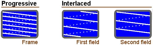
Note that two old standards (the legacy 8514/A and XGA systems) have very low frame rates, 44Hz, because they are interlaced systems (discussed next). To properly display these signals, a monitor must have sufficient range to synchronize with the field rate of these standards, which is twice the frame rate. InterlacingMost computer display systems use progressive scanning. That is, the system starts by displaying the first (top) line in the video image and then displays each subsequent line, one after the other down the screen. Televisions and video systems use interlaced scanning. Instead of scanning lines sequentially from top to bottom, each frame of the image is broken in half into two fields. One field consists of the odd-numbered lines of the image; the other the even-numbered lines. The electron beam sweeps across and down, illuminating every other line, and then starts from the top again and finishes with the ones it missed on the first pass. This technique achieves an apparent doubling of the frame rate. Instead of sweeping down the screen 30 times a second (the case of a normal television picture), the top-to-bottom sweep occurs 60 times a second. Whereas a 30-frames-per-second rate would noticeably flicker, the ersatz 60-frames-per-second rate does notat least not to most people under most circumstances. Some folks' eyes are not fooled, however, so interlaced images have earned a reputation of being flickery. Figure 24.8 compares progressive and interlaced scanning. Figure 24.8. Progressive versus interlaced scanning.
Interlacing is used on computer display signals to keep the necessary bandwidth down. A lower frame rate lowers the required bandwidth of the transmission channel. Although interlaced scanning should have been forgotten along with the 8514/A and original XGA display systems, it occasionally pops up in computer displaystypically low-priced monitors that claim high resolutions. Be wary of any monitor that specifies its maximum resolution as interlaced. BandwidthPerhaps the most common specification usually listed for any sort of monitor is bandwidth, which is usually rated in megahertz. Common monitor bandwidths stretch across a wide rangefigures from 12 to 200MHz are sometimes encountered. In theory, the higher the bandwidth, the higher the resolution and sharper the image displayed. In the case of color displays, the dot-pitch of the display tube is the biggest limit on performance. In a monochrome system, however, bandwidth is a determinant of overall sharpness. The computer display standards do not demand extremely wide bandwidths. Extremely large bandwidths are often superfluous. The bandwidth necessary in a monitor is easy to compute. A system ordinarily requires a bandwidth wide enough to address each individual screen dot plus an extra margin to allow for retrace times. (Retrace times are those periods in which the electron beam moves but does not displayfor instance, at the end of each frame when the beam must move from the bottom of the screen at the end of the last line of one frame back up to the top of the screen for the first line of the next frame.) A typical color display operating under the VGA standard shows 288,000 pixels (a 729x400-pixel image in text mode) 70 times per second, a total of 20.16 million pixels per second. An 800x600-pixel Super VGA display at 75Hz must produce 36 million pixels per second. Synchronizing signals require their own slice of monitor bandwidth. Allowing a wide margin of about 25 percent for retrace times, it can thus be seen that for most computer applications, a bandwidth of 16MHz is acceptable for TTL monitors, and 10MHz of bandwidth is sufficient for sharp composite video displays and figures well within the claims of most commercial products. For VGA, 25MHz is the necessary minimum. Multiplying the dot-clock by 25 percent yields an acceptable estimate of the bandwidth required in a monitor. For the standards IBM promulgated, the company listed actual bandwidth requirements. Table 24.4 summarizes these requirements and calculated estimates for various computer display standards. Although these estimates are calculated using the dot-clock of the display, the relationship between dot-clock and bandwidth is not as straightforward as the calculations imply. Because in real-world applications the worst-case display puts an illuminated pixel next to a dark one, the actual bandwidth required by a display system should be the dot-clock plus system overhead. A pair of on/off pixels exactly corresponds to the up and down halves of a single cycle. The higher bandwidth you calculate from the dot clock allows extra bandwidth that gives greater image sharpnesssharply defining the edges of a pixel requires square waves, which contain high-frequency components. Consequently, the multiplication of the dot-clock by display overhead offers a good practical approximation of the required bandwidth, even though the calculations are on shaky theoretical ground. Energy StarCompared to some of the things you might connect to your computer, a monitor consumes a modest amount of electricity. A laser printer can draw as much as a kilowatt when its fuser is operating. A typical computer requires 100 to 200 watts. A typical monitor requires only about 30 watts. Unlike the laser fuser, however, your monitor may stay on all day long, and an office may have hundreds of them, each continually downing its energy dosage. Those watts add up, not just in their power consumption but also their heat production that adds to the load on the office air conditioning. To help cut the power used by computer equipment, the Environmental Protection Agency started the Energy Star program, which seeks to conserve power while computers and their peripherals are in their idle states. For monitors, Energy Star means that the monitor powers down to a one of two lower power conditions or shuts off entirely when its host computer has not been used for awhile. Energy Starcompliant monitors have four operating modes: on, standby, suspend, and off. During normal operation when the monitor displays an active image generated by your computer, it is on. In standby mode, the monitor cuts off the electron beam in its CRT and powers down some of its electronics. It keeps the filament or heat of the CRT (the part that has to warm up to make the tube work) hot so that the monitor can instantly switch back to its on state. In suspend mode, the filament and most of the electronics of the monitor switch off. Only a small portion of the electronics of the monitor remain operational to sense the incoming signals, ready to switch the monitor back on when the need arises. This conserves most of the power that would be used by the monitor but requires the CRT to heat up before the monitor can resume normal operation. In other words, the monitor trades rapid availability for a reduction in power use. In off mode, the monitor uses no power but requires you to manually switch it on. To enable your computer to control the operating mode of your monitor without additional electrical connections, VESA developed its Display Power Management Standard (DPMS). This system uses the two synchronizing signals your video board supplies to your monitor to control its operating mode. To signal the monitor to switch to standby operation, your video card switches off only its horizontal sync signal. To signal the monitor to switch to suspend mode, your video board cuts both the video signal and the vertical sync but leaves the horizontal sync on. In off mode, all signals are cut off. Table 24.5 summarizes these modes.
Advanced operating systems monitor your system usage and send out the standby and/or suspend signals when you leave your system idle for a predetermined time. Your video driver software controls the DPMS signals. Note that screensaver software defeats the purpose of DPMS by keeping your system active even when it is not in use. You can trim your power usage by relying on DPMS rather than a screensaver to shut down your monitor. Many monitors made before the DPMS standard was created often incorporate their own power-saving mode that's initiated by a loss of the video signal for a predetermined time. In other words, these monitors sense when your screen is blank and start waiting. If you don't do something for, say, five minutes, the monitor switches to standby or suspend mode, no matter the state of the synchronizing signals. The DPMS system is designed so that these monitors, too, will power down (although only after the conclusion of both the DPMS and their own internal timing cycles). To enable the DPMS system under Windows, you must tell the operating system that your monitor is Energy Star compliant. If your monitor is in the Windows database, Windows will know automatically whether the monitor is compliant. You can also check the Energy Star compliance in the Change Display Settings screen. You must also activate the DPMS screen blanker from the Screen Saver tab of your Display Properties screen. IdentificationThe prevalence of multiscanning monitors with wildly different capabilities makes getting the most from your investment a challenge. You must be able to identify not only the display capabilities of the monitor, but also those of your video board, and then make the best possible match between them. If you're wrong, you won't get everything that you've paid for. Worse, you might not see anything intelligible on your screen. Worse still, you face a tiny chance of actually harming your monitor or video board. Hard-Wired CodingThe problem is neither new nor one that arose with multiscanning systems. When the VGA system was new, IBM developed a rudimentary system for letting its computers determine the type of monitor that was connectedlimited, of course, to the monitors IBM made. The system had limited capabilities. It could identify whether the monitor was monochrome or color and whether it met merely the VGA standard or advanced into higher-resolution territory. At the time, IBM only offered four monitors, and that modest range defined the extent of the selection. The IBM scheme was to use three of the connections between the monitor and the video board to carry signals identifying the monitor. These first signals were crudea simple binary code that put the signal wire either at ground potential or with no connection. Table 24.6 lists this coding system. Display Data ChannelThis rudimentary standard was not up to the task of identifying the wide range of monitor capabilities that became available in the years after the introduction of VGA. Yet adding true Plug-and-Play capabilities to your computer requires automatically identifying the type of monitor connected to your computer so that the display adapter (and the rest of the system) can be properly configured. To meet this challenge, VESA developed the Display Data Channel (DDC), an elaborate monitor-identification system based on the same connections as the early IBM system but with greatly enhanced signals and capabilities. Through the DDC, the monitor sends an Extended Display Identification (EDID) to your computer. In advanced form, the DDC moves data both ways between your monitor and your computer using either the I2C or ACCESS.bus serial interfaces. The DDC2B standard uses I2C bus signaling on two of the wires of the monitor connection to transfer data both ways between monitor and its attached video board. DDC2AB uses a full ACCESS.bus connection and protocol, which allow you to connect other computer peripherals (for example, your keyboard) to your monitor rather than the system unit. All levels of the DDC system gain information about your monitor in the same way. The monitor sends out the EDID as a string of serial bits on the monitor data line, pin 12. Depending on the level of DDC supported by the monitor, the EDID data stream is synchronized either to the vertical sync signal generated by the video board present on pin 14 of 15-pin video connectors or to a separate serial data clock (SCL) that's on pin 15 in DDC2 systems. One bit of data moves with each clock cycle. When the system uses vertical sync as the clock, the data rate will be in the range of 60 to 85Hz. With DDC-compliant monitors, your video board can temporarily increase the vertical sync frequency to up to 25KHz to speed the transmission of this data. Using the SCL signal when both the video board and monitor support it, data rates as high as 100KHz are possible. The serial data takes the form of nine-bit sequences, one per byte. The first eight bits encode the data, the most significant bit first. The last bit can be either a zero or one, at the choice of the monitor manufacturer. The only restriction is that the ninth bit must have the same value for every byte. The DDC system sends data from the monitor to your display adapter in 128-byte blocks. The first of these is the Extended Display Identification or EDID block. It is optionally followed by an Extended EDID block or additional proprietary manufacturer data blocks. Table 24.7 lists the structure of the basic EDID.
The header is always the same data pattern and serves to identify the EDID information stream. The vendor identification is based on EISA manufacturer identifications. The product identification is assigned by the manufacturer. It includes the month and year of manufacture of the monitor. The basic display parameters that EDID relays to your system include the maximum size of your monitor's display, expressed as the largest width and height of the image area. Your applications or operating system can use this information to automatically set the proper scaling for fonts displayed on the screen. The timing data includes a bit representing the ability to support each of the various VESA standards so that your system can determine the possible modes and frequencies your monitor can use. In addition to basic DDC support, VESA provides for two higher levels of standardization. The DDC2B system uses the Philips I2C signaling system to transfer data bidirectionally across the interface. The DDC2AB system includes full ACCESS.bus support that supplies a low-speed serial interconnection bus suitable for linking such peripherals as keyboards and pointing devices through the monitor. Because standard expansion buses do not provide suitable connections for routing ACCESS.bus signals, VESA has defined an auxiliary connector for the purpose, a five-pin "Berg" connector. Table 24.8 lists the signal assignments of this connector.
Monitors that are compliant with DDC use the same connectors as ordinary VGA displays. All the active video and synchronizing signals are located on the same pins of the connector, no matter the DDC level the monitor uses (or even if it doesn't use DDC at all). The only difference is the definition of the monitor-identification signals. DDC1 video boards sacrifice the Monitor ID Bit 1 pin, number 12, as a channel to receive identification data from your monitor. DDC2 systems make this signal bidirectional and take over pin 15 for use carrying the clock signal. In any case, pin 9 may be used to supply five volts for running accessory devices. Table 24.9 lists the signal assignments of the VGA 15-pin connector under DDC. Manual ConfigurationIf your monitor or video board does not support any level of the DDC specification, you will be left to configure your system on your own. In general, you won't need to perform any special configuration to a multiscanning monitor to match it to your video board if the signals from the video board are within the range of the monitor. That's the whole point of the multiscanning displayit adjusts itself to accommodate any video signal. That said, you may not get the most from your monitor. You might slight its refresh rate and quickly tire your eyes with a flickering display. Worse, you might exceed its capabilities and end up with a scrambled or blank screen. Windows includes its own configuration process that attempts to optimize the signals of your compliant video adapter with your monitor type. Windows already knows what video board you haveyou have to tell it when you install your video drivers. Without a DDC connection, however, Windows is cut off from your monitor, so you must manually indicate the brand and model of monitor you're using. You make these settings by clicking the Change Display Type button in the Settings tab of your Display properties menu. Click the button, and you see a dialog box like that shown in Figure 24.9. Figure 24.9. The Change Display Type dialog box in Windows.
InterfacesThe video system in your computer must somehow link up with the rest of its circuitry. In most display systems, the connection is intimate. It gives your computer's microprocessor the power to directly intervene and inject data, such as an image bitmap, right into the frame buffer. In nearly all of today's computers, the necessary link is an accelerated graphics port (AGP). Although based on the PCI expansion bus, AGP delivers substantially higher performance because it incorporates dedicated pipelined access to main memory. Thanks to its wide bandwidth, the design allows an accelerator chip on an AGP expansion board to use main memory for video functions such as z-buffering, texture-mapping, and alpha-blending. The AGP may be embedded and hidden in the circuitry of your computer when the display system is part of the motherboard or chipset. Otherwise, AGP takes the form of a single special slot on your desktop computer's motherboard. Accelerated Graphics PortThe AGP design originated in Intel Labs and was officially released as a standard (version 1.0) on July 31, 1996. As you might expect from a new bus design from Intel, it is based on the PCI design and follows basic PCI protocol and signaling. Because of its high speedpotentially four times that of today's PCIit uses its own, incompatible connector design and imposes tight restrictions on design layouts. On May 4, 1998, Intel revised the AGP design to version 2.0. The improvements were twofold. By adding a transfer mode, Intel created a new quadruple-speed mode for AGP. In addition, the new specification allows for lower-voltage operation. In addition to the 3.3-volt design of AGP 1.0, the revision allows for 1.5-volt operation as well. Although based on revision 2.1 of the PCI specifications, the AGP design goes beyond them with three innovations: pipelined memory that eliminates wait states, separate address and data lines on the bus to cut the necessary number of cycles per transfer, and a timing specification allowing operation at 133MHz across a 32-bit bus, thus allowing for throughput on the order of 500MBps. The actual clock speed of the AGP bus is 66MHz, matching the PCI 2.1 specs. To achieve the higher data rates, the AGP system relies on more exotic technologies, discussed in the 2x transfer mode and 4x transfer mode sections, later. The AGP shares the same physical address space for memory with the PCI system and microprocessor. It uses a 32-bit address bus that can handle up to a 4GB address range. Matching its 32-bit data bus, AGP transfers always move data in eight byte blocks, double the granularity of standard PCI transfers (which slices data into four bytes blocks). To accommodate smaller data types, the AGP interface can also use PCI transfer modes. Despite its PCI foundation, AGP has its own set of commands and transfer protocol. The AGP interface hardware supports both the AGP transfers and traditional PCI transfers as separate modes. Unlike PCI, where address and data cycles are intimately linked, the AGP modes disconnect them. This allows other data to intervene in between. This design allows the system to keep the pipeline filled. Each access request across the AGP is sent to a queue while it awaits the transfer of its associated data. The AGP devices track the access requests and data in their hardware. Access requests in the queue are prioritized into high- and low-priority subqueues. PCI transfers have their own queue. The AGP design allows for a maximum of 256 transactions in the pipeline at once, although hardware capabilities will further constrain the pipeline. When the Plug-and-Play system sets up the AGP board, the AGP hardware reports the maximum depth that the pipeline can support in its host computer. On the other hand, the AGP transfer modes allow access only to memory. They do not link to input/output ports or configuration memory. In addition, to help the AGP achieve its high speed, its design cuts it free from cache snooping, so changes made through AGP are not necessarily reflected in the memory cache. ArchitectureAGP clearly shows the new role of video in the future of the computer. Through AGP, video is given its own dedicated interface and connection. It does not share a bus with expansion boards or even memory. It has a direct reach to the high holy sanctum of the computer, the microprocessor and chipset. In effect, the AGP is a fourth bus in a modern computer, added to the expected compatibility bus (ISA), high-speed expansion bus (PCI), and memory bus. The signals for AGP arise in the same system-control logic that links to the PCI bridge and main memory in the computer. As shown in Figure 24.10, the AGP design gives the graphics chip of a computer the same direct connection with the chipset as honors the microprocessor, PCI bridge, and memory system. Figure 24.10. Block diagram showing the role of AGP in modern system architecture.
AGP operates solely between two devices. By design, one of these must be the system memory controller, which is normally part of the computer's chipset. To the AGP system, the chipset is the target device, and AGP transfers are controlled by the graphics board at the other end of the connection, which is the master. In PCI transfer modes, the host chipset operates as a PCI sequencer, which is capable of service as both master and target. The video board only needs to operate as a PCI target, although it may also have master functions as well. OperationIntel envisioned that the AGP would be used in two different ways. Its DMA model pictured AGP would be used as a fast channel for moving large blocks of data between a dedicated frame buffer and main system memory. Your computer's graphic chip would work conventionally, working in the memory on the expansion board, carrying out most operations directly in the frame buffer. The system would use DMA transfers across the AGP to move bit-image data from system memory to the frame buffer. The execute model sees the AGP as a means of connecting the graphics accelerator to main memory. The accelerator chip on the video board can use main memory for execution of high-level functions such as antialiasing and 3D rendering. The graphics chip would use the AGP to draw data from system memory and hold intermediate results, loading the final data of the image into the local frame buffer. In either case, transfers are mediated in the same way. First, either end of the connection negotiates to use the interface. When operating in its native AGP mode, the graphics controller starts each transaction by making an access request to the system board chipset. The chipset then schedules its action on the request, working around other tasks that involve the bus. The chipset can accumulate several graphics requests and begin to process them while waiting for the actual data transfer to take place. In effect, the processing steps involved in the transfer requests are pipelined much like instructions in an advanced microprocessor. The transfer requests in the pipeline are split into two queues, one with high priority and one with low priority, for each read and write request. The AGP system puts the responsibility for tracking the status of all the transfers on the graphics controller requesting them, and the controller determines the number of requests waiting in each queue. The chipset processes the requestfor example, transferring data from system memory to the frame bufferas free time in the system allows it. It can process requests from the various queues as system resources allow, so it may interleave the processing of read and write requests. When operating in its PCI mode, the graphics controller acts like any PCI device. However, the PCI transfers are not pipelined like the native AGP transactions. The signals used for AGP transfers are built on a foundation of the PCI bus. The AGP standard augments the PCI standard with special control signals Intel terms sideband signals. They alter the timing of the PCI bus to allow higher data throughput. The PCI data and bus control lines still channel information during AGP transfers, but a new signal termed PIPE# defines the AGP transfer, much as the FRAME# signal defines PCI transfers. When the PIPE# signal is active, the system operates in the AGP 2x transfer mode and moves data across the bus twice during each cycle. Request queuing, pipelining, parallel execution, and the double-time transfer cycle all contribute to the higher throughput of the AGP interface. AGP-defined protocols (for example, pipelining) are overlaid on the PCI bus at a time and in a manner that a PCI bus agent (non-AGP) would view the bus as idle. Both pipelined access requests (read or write) and resultant data transfers are handled in this manner. The AGP interface uses both PCI bus transactions without change, as well as AGP pipelined transactions as defined herein. Both of these classes of transactions are interleaved on the same physical connection. The access request portion of an AGP transaction (bus command, address, and length) is signaled differently than is a PCI address phase. The information is still transferred on the AD and C/BE# signals of the bus, as is the case with PCI 6, but is identified or framed with a new control signal, PIPE#, in a similar way to which PCI address phases are identified with FRAME#. 2x Transfer ModeFor high-performance systems in which the 266MBps potential of basic AGP is inadequate, the original AGP specification allowed for higher-speed transfers in its 2x transfer mode. Using the proven technique called double-clocking, 2x mode pushes the maximum potential throughput of the AGP system to 533MBps. Double-clocking makes the clock signal do double duty, keying transfers to both its leading and trailing edges. That is, the transition marking the beginning of the clock signal triggers one transfer across the bus, and the transition ending the clock pulse triggers another. In most logic systems and basic AGP mode, only the leading edge of the clock signals valid data, allowing the making of a transfer. To improve the reliability of 2x transfer mode, it uses three strobe signals rather than the clock itself. The clock signal originates in your computer as part of its array of PCI signals. In contrast, the device sending data generates the strobe signals. When your computer sends data to the AGP board, it creates the strobes. When the AGP board sends data to your computer, it creates the strobes. Because the sending device generates both the data and strobe signals, the timing relationship between the two can be more precisely controlled. The strobe signals appear only within the interconnection between the AGP transmitting and receiving circuits and the hardware connection between them. In AGP terminology, this is the inner loop. The rest of the AGP system is the outer loop. The specification defines individual strobe signals for the low and high 16 bits of the AGP bus as well as the sideband. The AGP circuitry issues the strobe signals at the same frequency as the AGP clock, but the specification more rigidly defines the timing of the strobes. The high and low phases of the strobe signal are equal, so leading and trailing edges of the signals are evenly spaced and transfers keyed to the edges occur uniformly. 4x Transfer ModeIn enhancing the performance of AGP, the Intel engineers faced a major problem. The original design already strained at the high-frequency limit of the connector system. Increasing the speed of AGP would require a redesign with expensive new technologies. To avoid most of these issues, the Intel engineers kept their changes inside the inner loop, designing a more elaborate strobe system. To create 4x transfer mode, Intel's engineers doubled the frequency of the strobe signals and double-clocked the data keyed to them. This change again doubles the potential throughput of the system, yielding a maximum rate of 1066MBps. With the increase in strobe frequency comes a need for a tighter definition of the timing of the signals. Intel created the necessary precision by adding three more strobe signals. Each one is paired with one of the 2x transfer mode signals but is the opposite polarity, turning each strobe into a differential pair. When one of the strobes in a pair transitions from high to low, the other moves from low to high. At one instant during the paired transitions, at approximately midway between them, the voltage values of the two signals are equalon a timing chart, the values cross. The 4x transfer mode keys each transfer to one of these crossings. Because these crossings occur twice in each strobe cycle and the strobe frequency is twice the basic AGP clock frequency, transfers occur at four times the basic AGP rate. Intel took another step to help AGP achieve the speed required by 4x transfer mode. It lowered the voltage of the signals, which helps deal with the capacitance inherent in any bus system. All AGP boards that operate in AGP 4x transfer mode must use 1.5-volt signaling. UMAUnified Memory Architecture (UMA) is an alternate way to design a computer for lower-cost construction. It actually can have a beneficial effect on video performance. Because the frame buffer is integrated into the main memory of the computer, bitmaps don't have to cross any I/O bus at all. Of course, the memory used by the frame buffer cannot also be used by programs, but today's memory prices make this loss of storage almost inconsequential. To provide a common standard to which designers could create the electrical and logical interface between the video system using UMA and the core logic of a computer, VESA developed its own standard called VESA Unified Memory Architecture (VUMA). First published in March, 1996, VUMA allows for adding external devices to your computer that can share direct access to its main memory system to use it as a frame buffer. Although UMA has become popular in low-cost computers, even with this standard, add-on devices that use the technology have not become popular. Monitor Interfacing and ConnectorsThe video connection carries the image between your video board and monitor. Monitors can be grouped by the display standard they support, mostly based on the display adapter card they are designed to plug into. One basic guide that helps you narrow down the compatibility of a display just by inspecting its rear panel is the input connector used by the monitor. After all, if you cannot plug a monitor into your computer, odds are it is not much good to you. You'll likely encounter one of three styles of connector on the back of your computer. These include legacy connectors used by display systems too ancient to worry about, analog system used by the majority of today's display systems, and new digital interfaces that are beginning to appear on the market and mark the look (and connection) of things to come. Legacy ConnectorsThe first video connector used by computers was the nine-pin D-shell connector, as shown in Figure 24.11. It is now used only by legacy video systems and serves mostly as a warning that you may encounter trouble in trying to match your video system to a monitor. Figure 24.11. A nine-pin D-shell jack used by legacy video systems.
Analog Connection SystemsThree styles of connectors are shared by different computer video standards. By name, these three connectors are the RCA-style pin jack, the nine-pin D-shell, and the 15-pin "high-density" D-shell. In addition, some high-resolution monitors use three or more BNC connectors for their input signals. Pin JacksThe bull's-eye jack used on stereo and video equipment is used by most manufacturers for the composite video connections in computer display systems, although a wealth of monitors and television sets made by innumerable manufacturers also use this connector. This connector does give you many choices for alternate displaysthat is, if you don't mind marginal quality. Composite monitors (those dealing with the composite video and NTSC color only) rank among the most widely available and least expensive in both color and monochrome. Even better quality television sets have such jacks, shown in Figure 24.12, available. Figure 24.12. A pin jack used by composite video signals.
Although you can use any composite video display with a CGA or compatible color card, the signal itself limits the possible image quality to okay for monochrome, acceptable for 40-column color, and unintelligible for 80-column color. Nevertheless, a composite video displayalready a multipurpose devicebecomes even more versatile with a computer input. Daisy-ChainingA side benefit of pin plug/composite video displays is that most have both input and output jacks. These paired jacks enable you to daisy-chain multiple monitors to a single video output. For example, you can attach six composite video monitors to the output of your computer for presentations in the classroom or boardroom. In many cases, the jacks just loop through the display (that is, they connect together). The display merely bridges the input video signal and alters it in no other manner. You can connect a nearly unlimited number of monitors to these loop-through connections with no image degradation. Some monitors, however, buffer their outputs with a built-in video amplifier. Depending on the quality of the amplifier, daisy-chaining several of these monitors can result in noticeable image degradation. One way to tell the difference is by plugging the output of the display into the output of your computer. Most amplifiers don't work backwards, so if the display has a buffering amplifier, nothing appears onscreen. If you do get an image comparable to the one you get when plugging into the input jack, the signal just loops through the display. Analog Voltage LevelThe specifications of composite monitors sometimes include a number describing the voltage level of the input signal. This voltage level can be important when selecting a composite display because all such monitors are essentially analog devices. In analog monitors, the voltage level corresponds to the brightness the electron beam displays onscreen. A nominal one-volt peak-to-peak input signal is the standard in both the video and computer industries and should be expected from any composite monitor. The VGA system requires a slightly different level0.7 volts. TerminationFor proper performance, a composite video signal line must be terminated by an impedance of 75 ohms. This termination ensures that the signal is at the proper level and that aberrations do not creep in because of an improperly matched line. Most composite input monitors (particularly those with separate inputs and outputs) feature a termination switch that connects a 75-ohm resistor across the video line when turned on. Only one termination resistor should be switched on in any daisy-chain, and it should always be the last monitor in the chain. If you watch a monitor when you switch the termination resistor on, you'll notice that the screen gets dimmer. That's because the resistor absorbs about half the video signal. Because composite video signals are analog, they are sensitive to voltage level. The termination cuts the voltage in half and consequently dims the screen by the same amount. Note that the dim image is the proper one. Although bright might seem better, it's not. It may overload the circuits of the monitor or otherwise cause erratic operation. Composite monitors with a single video input jack and no video output usually have a termination resistor permanently installed. Although you might try to connect two or more monitors to a single CGA composite output (with a Y cable or adapter), doing so would be unwise. With each additional monitor, the image gets dimmer (the signal must be split among the various monitors), and the CGA adapter is required to send out increasing current. The latter could cause the CGA to fail. VGA ConnectorsThe most common connector on computer monitors is the 15-pin high-density D-shell connector. Originally put in use by IBM for its first VGA monitors, this connector has become adopted as an industry standard for all but the highest performance computer displays. Because the signals generated by VGA are so different from those of previous IBM display systems, IBM finally elected to use a different, incompatible connector so the wrong monitor wouldn't be plugged in with disastrous results. Although only nine connections are actually needed by the VGA system (11 if you give each of the three video signals its own ground return as IBM specifies), the new connector is equipped with 15 pins. It's roughly the same size and shape as a nine-pin D-shell connector, but before IBM's adoption of it, this so-called high-density 15-pin connector was not generally available. Figure 24.13 shows this connector. Figure 24.13. A 15-pin mini D-shell connector used by VGA and similar video systems.
In addition, to allow for four video signals (three primary colors and separate sync) and their ground returns, the VGA connector provides a number of additional functions. In the original VGA design, it enabled the coding of both monitor type and the line count of the video signal leaving the display adapter. The modern adaptation of the connector to the VESA DDC standard redefines several pins for carrying data signals, as noted earlier. Table 24.10 lists the signal assignments of the VGA connector. IBM's 8514 and 8515 displays as well as 8514/A and XGA display adapters also use the same connector, even though they at times use different signals. Again, however, IBM has incorporated coding in the signals to ensure that problems do not arise. The 8514/A and XGA adapters can sense the type of display connected to them and do not send out conflicting signals. The 8514 and 8515 monitors operate happily with VGA signals, so problems do not occur if they are plugged into an ordinary VGA output. The advantage of the 15-pin connector is convenience. One cable does everything. On the downside, the connector is not arranged for proper high-speed operation, and its deficiencies can limit high-frequency performance, which in video terms equates to sharpness when operating at high resolutions and refresh rates. Consequently, the highest resolution systems often forego the 15-pin connector for separate BNC connectors for each video channel. BNC ConnectorsTrue high-resolution systems use a separate coaxial cable for every signal they receive. Typically, they use BNC connectors to attach these to the monitor. They have one very good reason: Connectors differ in their frequency-handling capabilities, and capacitance in the standard 15-pin high-density D-shell connector can limit bandwidth, particularly as signal frequencies climb into the range above 30MHz. BNC connectors are designed for frequencies into the gigahertz range, so they impose few limits on ordinary video signals. Monitors can use either three, four, or five BNC connectors for their inputs. Figure 24.14 shows an array of five BNC connectors on the rear of a monitor. Figure 24.14. A monitor with five BNC connectors for input.
A three-connector system integrates both horizontal and vertical synchronizing signals with the green signal. The resulting mix is called sync-on-green. Others use three connectors for red, green, and blue signals and a fourth for the horizontal and vertical sync signals combined together. This scheme is called composite sync. Five-connector systems use three color signals, one for horizontal sync, and one for vertical sync. These are called separate sync systems. Digital Video InterfaceFlat-panel displays made the need for a high-performance digital display interface obvious. Analog-interface flat panels work but are only an interim solution. Among the other problems with the standard analog links so popular on today's monitors, one stands in the way of getting truly high-resolution images on your monitorlimited bandwidth. The now-dominant VGA connector has a maximum bandwidth of about 150MHz, so it already constrains the quality of some display systems. Conventional high-frequency video connectors (primarily BNC) require a separate cable for each video signal and allow no provisions for auxiliary functions such as monitor identification. Achieving a single standard has been problematic for the industry, however. In the last few years, various groups have developed at least three specifications, all promoted as "standards." Despite the infighting among the promoters of each, the three are not in competition, however, but represent the evolution of what will likely be the dominant standard for the future, the Digital Video Interface (DVI). In late 1998, Intel rounded up the usual suspects to work on yet another digital display standard. The result was the Digital Display Working Group, initially comprising representatives from both the Plug and Display and Digital Flat Panel (DFP) connector campsIntel, Compaq, Fujitsu, Hewlett-Packard, IBM, NEC, and Silicon Image. The working group took the better features of each of the two earlier standards and developed the Digital Video Interface as kind of the "greatest hits" of monitor connectors. The standard was adopted and published by VESA as DVI version 1.0 on April 2, 1999. Number Nine Visual Technology demonstrated the first product to use the interface, the SR9 graphics adapter, on May 19, 1999. DVI shares the connector design and some of the non-video data signals with Plug and Display, but it breaks off the integral USB port from the connector. Although the DVI standard does not preclude USB in displays, to do so a separate connection must be used for the USB signals. Although DVI uses the same Transition Minimized Differential Signaling (TMDS) signals as Plug and Display and DFP, it doubles the effective bandwidth of these signals with the simple expedient of using two of them. Both are locked to the single clock channel provided by the interface, so they are automatically synchronized to each other. Each color signal has two signals, which are interleaved so that data is spread between the two channels of a given color, creating what is essentially a parallel connection. Display systems may use either the one-channel system or the two-channel system, but the DVI specification draws a hard line between the two. Signals requiring a bandwidth of less than 165MHz must use the single-channel system. Systems requiring larger bandwidths must use two channels. The three signal paths of DVI are not named with colors, although they correspond to red, green, and blue data. Each signal path actually carries three interleaved channels of data. The signal path used by blue data, for example, also carries a horizontal synchronizing signal and a vertical synchronizing signal. The two channels in the remaining pair of signal paths are currently reserved and have no assigned function. Analog video is an optional part of DVI. Rather than shape, the DVI connector uses the cross-pin in the connector as a key for the presence of analog signals. The same connector can be used for all-analog or all-digital systems. Analog signals, when present, are located in the four quadrants around the keying cross in the connector. |
| [ Team LiB ] |
|