| [ Team LiB ] |
|
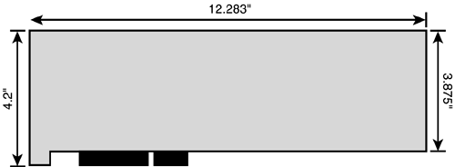
PCI BoardsThe PCI specification defines several variations on the basic expansion board. The standard defines two official sizes of board, each with three connector arrangements (5 volt, 3.3 volt, and dual voltage). The dimensions of the two board sizes may seem arbitrary, but they owe their heritage to traditional ISA expansion boards. The similarity arose because early PCI-based computers also hosted ISA expansion boards for compatibility reasons. The ISA boards defined the size of the computer, and PCI boards were tailored to fit the space. DimensionsA full-size PCI expansion board measures 12.283 inches (312 mm) long. The main body of the board is about 3.875 inches high, although the expansion edge connector and a short skirt extend the width of the board to 4.2 inches (106.68 mm). The critical reference dimension is the centerline of the notch in the expansion connector, which is displaced 4.113 inches (104.47 mm) from the back edge (retaining bracket side) of the board. Figure 30.1 shows the dimensions of a full-size PCI board in 5-volt configuration. Cards designed for 3.3 volts or universal operation will differ in contact number and placement but not overall size. Figure 30.1. Primary dimensions of a full-size 5-volt PCI expansion board.
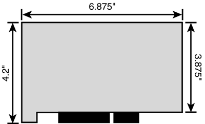
PCI also defines a short board, about half the length of a full-size board at 6.875 inches (174.63 mm) front to back. All other vital dimensions, including the distance from rear edge to the registration notch in the expansion connector, are identical to a full-size board. Figure 30.2 shows the dimensions of a PCI short card. Figure 30.2. Primary dimensions of a 5-volt PCI short card.
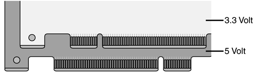
No matter the length of the board, PCI specifies a maximum thickness. The components on a PCI board can rise no more than 0.570 inches above the substrate. On the other side of the board, components can protrude no more than 0.105 inches. Add those heights to the nominal 0.100-inch thickness of the substrate, and PCI provides for 0.025 inches of safety gap between board components, with standard slot spacing of 0.800 inches. ConnectorsTo accommodate the development of low-voltage "green" computers, PCI specifies two connector types and three different connector regimes: a 5-volt connector for today's prevailing circuit designs, a 3.3-volt connector for low-power designs, and the capability to combine both connectors on a single expansion board for a smooth transition between designs. A key on 5-volt sockets (blocking pins 50 and 51) prevents the insertion of 3.3-volt boards. (Five-volt boards have a slot corresponding to the key.) A key on 3.3-volt sockets (at pins 12 and 13) restricts the insertion to correspondingly slotted 3.3-volt boards. Boards capable of discriminating the two voltage regimes have slots in both places, as shown in Figure 30.3. Figure 30.3. Edge connectors for 5 and 3.3 volt PCI cards (32 bit).
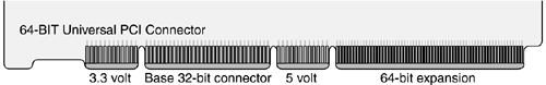
The 64-bit implementation of PCI extends the edge connector to accommodate the additional required signals. Figure 30.4 shows this extended connector and the full implementation of all of its options. Figure 30.4. The 64-bit universal PCI edge connector.
|
| [ Team LiB ] |
|