| [ Team LiB ] |
|
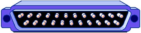
RS-232C Serial PortsThe day you win the vmega-lottery and instantly climb into wealth and social status, you may be tempted to leave your old friends to belch and scratch while drinking someone else's beer. But it's hard to leave old friends behind, particularly when you need someone to watch the house during your 'round-the-world cruise. So it is with the classic RS-232C port. It's got so many bad habits it's hard to talk about in polite company, but it's just too dang useful to forget about. The serial port is truly the old codger of computer interfaces, a true child of the '60s. An industry trade group, the Electronics Industry Association (EIA) hammered out the official RS-232C specification in 1969, but the port had been in use for years at the time. It found ready acceptance on the first personal computer because no other electronic connection for data equipment was so widely used. The ports survive today because some folks still want to connect gear they bought in 1969 to their new computers. Electrical OperationRS-232C ports are asynchronous. They operate without a clock signal. But in order for two devices to communicate they need at least a general idea of what rate to expect data. Consequently, you must set the speed of each RS-232C port before you begin communicating, and the speeds of any two connected ports must match. You have quite a wide variety to choose from. The serial ports in computers generally operate at any speed in the odd-looking sequence that runs 150, 300, 600, 1200, 2400, 4800, 9600, 19,200, 38,400, 57,600, and 115,200 bits per second. The RS-232C moves data one byte at a time. To suit its asynchronous nature, each byte requires its own packing into a serial frame. In this form the typical serial port takes about a dozen bits to move a bytea frame comprises two start bits, eight data bits, one parity bit, and one stop bit to indicate the end of the frame. As a result, a serial port has overhead of about one-third of its potential peak data rate. A 9600 bit per second serial connection actually moves text at about 800 characters per second (6400bps). A basic RS-232C connection needs only three connections: one for sending data, one for receiving data, and a common ground. Most serial links also use hardware flow-control signals. The most common serial port uses eight separate connections. RS-232C port use single-ended signaling. Although this design simplifies the circuitry to make the ports, it also limits the potential range of a connection. Long cable runs are apt to pick up noise and blur high-data-rate signals. You can probably extend a 9600bps connection to a hundred feet or more. At a quarter mile, you'll probably be down to 1200 or 300bps (slower than even cheap printers can type). Because the RS-232C port originated in the data communications rather than computer industry, some of its terminology is different from that used to describe other ports. For example, the low and high logic states are termed space and mark in the RS-232C scheme. Space is the absence of a bit, and mark is the presence of a bit. On the serial line, a space is a positive voltage; a mark is a negative voltage. In other words, when you're not sending data down a serial line, it has an overall positive voltage on it. Data will appear as a serial of negative-going pulses. The original design of the serial port specification called for the voltage to shift from a positive 12 volts to negative 12 volts. Because 12 volts is an uncommon potential in many computers, the serial voltage often varies from positive 5 to negative 5 volts. ConnectorsThe physical manifestation of a serial port is the connector that glowers on the rear panel of your computer. It is where you plug your serial peripheral into your computer. And it can be the root of all evilor so it will seem after a number of long evenings during which you valiantly try to make your serial device work with your computer, only to have text disappear like phantoms at sunrise. Again, the principal problem with serial ports is the number of options they allow designers. Serial ports can use either of two styles of connectors, each of which has two options in signal assignment. Worse, some manufacturers venture bravely in their own directions with the all-important flow-control signals. Sorting out all these options is the most frustrating part of serial port configuration. 25-PinThe basic serial port connector is called a 25-pin D-shell. It earns its name from having 25 connections arranged in two rows that are surrounded by a metal guide that roughly takes the form of a letter D. The male variety of this connectorthe one that actually has pins inside itis normally used on computers. Most, but hardly all, serial peripherals use the female connector (the one with holes instead of pins) for their serial ports. Although both serial and parallel ports use the same style 25-pin D-shell connectors, you can distinguish serial ports from parallel ports because on most computers the latter use female connectors. Figure 11.8 shows the typical male serial port DB-25 connector that you'll find on the back of your computer. Figure 11.8. The male DB-25 connector used by serial ports on computers.
Although the serial connector allows for 25 discrete signals, only a few of them are ever actually used. Serial systems may involve as few as three connections. At most, computer serial ports use 10 different signals. Table 11.7 lists the names of these signals, their mnemonics, and the pins to which they are assigned in the standard 25-pin serial connector.
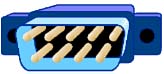
Note that in the standard serial cable, the signal ground (which is the return line for the data signals on pins 2 and 3) is separated from the chassis ground on pin 1. The chassis ground pin is connected directly to the metal chassis or case of the equipment, much like the extra prong of a three-wire AC power cable, and it provides the same protective function. It ensures that the case of the two devices linked by the serial cable are at the same potential, which means you won't get a shock if you touch both at the same time. As wonderful as this connection sounds, it is often omitted from serial cables. On the other hand, the signal ground is a necessary signal that the serial link cannot work without. You should never connect the chassis ground to the signal ground. Nine-PinIf nothing else, using a 25-pin D-shell connector for a serial port is a waste of at least 15 pins. Most serial connections use fewer than the complete 10; some as few as four with hardware handshaking, and three with software flow control. For the sake of standardization, the computer industry sacrificed the cost of the other unused pins for years until a largeror smaller, depending on your point of viewproblem arose: space. A serial port connector was too big to fit on the retaining brackets of expansion boards along with a parallel connector. In that all the pins in the parallel connector had an assigned function, the serial connector met its destiny and got miniaturized. Moving to a nine-pin connector allowed engineers to put connectors for both a serial port and a parallel port on the retaining bracket of a single expansion board. This was an important concern because all ports in early computers were installed on expansion boards. Computer makers could save the cost of an entire expansion board by putting two ports on one card. Later, after most manufacturers moved to putting ports on computer motherboards, the smaller port design persisted. As with the 25-pin variety of serial connector, the nine-pin serial jack on the back of computers uses a male connector. Figure 11.9 shows the nine-pin male connector that's used on some computers for serial ports. Figure 11.9. The male DB-9 plug used by AT-class serial devices.
Nine-pin connectors necessarily have different pin assignments than 25-pin connectors. Table 11.8 lists the signal assignments on the most common nine-pin implementation of the RS-232C port.
Other than the rearrangement of signals, the nine-pin and 25-pin serial connectors are essentially the same. All the signals behave identically, no matter the size of the connector on which they appear. SignalsSerial communications is an exchange of signals across the serial interface. These signals involve not just data but also the flow-control signals that help keep the data flowing as fast as possiblebut not too fast. First, we'll look at the signals and their flow in the kind of communication system for which the serial port was designedlinking a computer to a modem. Then we'll examine how attaching a serial peripheral to a serial port complicates matters and what you can do to make the connection work. DefinitionsAs with space and mark, RS-232C ports use other odd terminology. Serial terminology assumes that each end of a connection has a different type of equipment attached to it. One end has a data terminal connected to it. In the old days when the serial port was developed, a terminal was exactly thata keyboard and a screen that translated typing into serial signals. Today, a terminal is usually a computer. For reasons known but to those who revel in rolling their tongues across excess syllables, the term Data Terminal Equipment is often substituted. To make matters even more complex, many discussions talk about DTE devices, which means exactly the same thing as data terminals. The other end of the connection has a data set, which corresponds to a modem. Often engineers substitute the more formal name Data Communication Equipment or talk about DCE devices. The distinction between data terminals and data sets (or DTE and DCE devices) is important. Serial communications were originally designed to take place between one DTE and one DCE, and the signals used by the system are defined in those terms. Moreover, the types of RS-232 serial devices you wish to connect determines the kind of cable you must use. First, however, let's look at the signals; then we'll consider what kind of cable you need to carry them. Transmit DataThe serial data leaving the RS-232 port travels on what is called the Transmit Data line, which is usually abbreviated TXD. The signal on it comprises the long sequence of pulses generated by the UART in the serial port. The data terminal sends out this signal, and the data set listens to it. Receive DataThe stream of bits going the other directionthat is, coming in from a distant serial portgoes through the ReceiveData line (usually abbreviated RXD) to reach the input of the serial port's UART. The data terminal listens on this line for the data signal coming from the data set. Data Terminal ReadWhen the data terminal is able to participate in communicationsthat is, it is turned on and in the proper operating modeit signals its readiness to the data set by applying a positive voltage to the Data Terminal Ready line, which is abbreviated DTR. Data Set ReadyWhen the data set is able to receive datathat is, it is turned on and in the proper operating modeit signals its readiness by applying a positive voltage to the Data Set Ready line, which is abbreviated DSR. Because serial communications must be "two way," the data terminal will not send out a data signal unless it sees the DSR signal coming from the data set. Request to SendWhen the data terminal is on and capable of receiving transmissions, it puts a positive voltage on its Request to Send line, usually abbreviated RTS. This signal tells the data set that it can send data to the data terminal. The absence of an RTS signal across the serial connection will prevent the data set from sending out serial data. This allows the data terminal to control the flow of the data set to it. Clear to SendThe data set, too, needs to control the signal flow from the data terminal. The signal it uses is called Clear to Send, which is abbreviated CTS. The presence of the CTS signal in effect tells the data terminal that the coast is clear and the data terminal can blast data down the line. The absence of a CTS signal across the serial connection will prevent the data terminal from sending out serial data. Carrier DetectThe serial interface standard shows its roots in the communication industry with the Carrier Detect signal, which is usually abbreviated CD. This signal gives a modem, the typical data set, a means of signaling to the data terminal that it has made a connection with a distant modem. The signal says that the modem or data set has detected the carrier wave of another modem on the telephone line. In effect, the carrier detect signal gets sent to the data terminal to tell it that communications are possible. In some systems, the data terminal must see the carrier detect signal before it will engage in data exchange. Other systems simply ignore this signal. Ring IndicatorSometimes a data terminal has to get ready to communicate even before the flow of information begins. For example, you might want to switch your communications program into answer mode so that it can deal with an incoming call. The designers of the serial port provided such an early warning in the Ring Indicator signal, which is usually abbreviated RI. When a modem serving as a data set detects ringing voltagethe low-frequency, high-voltage signal that makes telephone bells ringon the telephone line to which it is connected, it activates the RI signal, which alerts the data terminal to what's going on. Although useful in setting up modem communications, you can regard the ring indicator signal as optional because its absence usually will not prevent the flow of serial data. Signal GroundAll the signals used in a serial port need a return path. The signal ground provides this return path. The single ground signal is the common return for all other signals on the serial interface. Its absence will prevent serial communications entirely. Flow ControlSerial ports can use both hardware and software flow control. Hardware flow control involves the use of special control lines that can be (but don't have to be) part of a serial connection. Your computer signals whether it is ready to accept more data by sending a signal down the appropriate wire. Software flow control involves the exchange of characters between computer and serial peripherals. One character tells the computer your peripheral is ready, and another warns that it can't deal with more data. Both hardware and software flow control take more than one form. As a default, computer serial ports use hardware flow control (or hardware handshaking). Most serial peripherals do, too. In general, hardware flow control uses the Carrier Detect, Clear to Send, and Data Set Ready signals. Software flow control requires your serial peripheral and computer to exchange characters or tokens to indicate whether they should transfer data. The serial peripheral normally sends out one character to indicate it can accept data and a different character to indicate that it is busy and cannot accommodate more. Two pairs of characters are often used: XON/XOFF and ETX/ACK. CablesThe design of the standard RS-232 serial interface anticipates that you will connect a data terminal to a data set. When you do, all the connections at one end of the cable that link them are carried through to the other endpin for pin, connection for connection. The definitions of the signals at each end of the cable are the same, and the function and direction of travel (whether from data terminal to data set or the other way around) of each are well defined. Each signal goes straight through from one end to the other. Even the connectors are the same at either end. Consequently, a serial cable should be relatively easy to fabricate. In the real world, nothing is so easy. Serial cables are usually much less complicated or much more complicated than this simple design. Unfortunately, if you plan to use a serial connection for a printer or plotter, you have to suffer through the more complex design. Straight-Through CablesSerial cables are often simpler than pin-for-pin connections from one end to the other because no serial link uses all 25 connector pins. Even with the complex handshaking schemes used by modems, only nine signals need to travel from the data terminal to the data set, computer to modem. (For signaling purposes, the two grounds are redundantmost serial cables do not connect the chassis ground.) Consequently, you need only make these 10 connections to make virtually any data terminaltodata set link work. Assuming you have a 25-pin D-shell connector at either end of your serial cable, the essential pins that must be connected are 2 through 8, 20, and 22 on a 25-pin D-shell connector. This is usually called a nine-wire serial cable because the connection to pin 7 uses the shield of the cable rather than a wire inside. With nine-pin connectors at either end of your serial cable, all nine connections are essential. Not all systems use all the handshaking signals, so you can often get away with fewer connections in a serial cable. The minimal case is a system that uses software handshaking only. In that case, you need only three connections: Transmit Data, Receive Data, and the signal ground. In other words, you need only connect pins 2, 3, and 7 on a 25-pin connector or pins 2, 3, and 5 on a nine-pin serial connector (providing, of course, you have the same size connector at each end of the cable). Although cables with an intermediary number of connections are often available, they are not sufficiently less expensive than the nine-wire cable to justify the risk and lack of versatility. Therefore, you should limit your choices to a nine-wire cable for systems that use hardware handshaking or three-wire cables for those that you're certain use only software flow control. Manufacturers use a wide range of cable types for serial connections. For relatively low data rates and reasonable lengths of serial connections, you can get away with just about anything, including twisted-pair telephone wire. To ensure against interference, you should use shielded cable, which wraps a wire braid or aluminum-coated plastic film around inner conductors to prevent signals leaking out or in. The shield of the cable should be connected to the signal ground. (Ideally, the signal ground should have its own wire, and the shield should be connected to the chassis ground, but most folks just don't bother.) Adapter CablesIf you need a cable with a 25-pin connector at one end and a nine-pin connector at the other, you cannot use a straight-through design, even when you want to link a data terminal to a data set. The different signal layouts of the two styles of connectors are incompatible. After all, you can't possibly link pin 22 on a 25-pin connector to a nonexistent pin 22 on a nine-pin connector. This problem is not uncommon. Even though the nine-pin connector has become a de facto standard on computers, most other equipment, including serial plotters, printers, and modems, has stuck with the 25-pin standard. To get from one connector type to another, you need an adapter. The adapter can take the form of a small assembly with a connector on each end of an adapter cable, typically from six inches to six feet long. Crossover CablesAs long as you want to connect a computer serial port that functions to a modem, you should have no problem with serial communications. You will be connecting a data terminal to a data set, exactly what engineers designed the serial systems for. Simply sling a cable with enough conductors to handle all the vital signals between the computer and modem andvoilàserial communications without a hitch. Try it, and you're likely to wonder why so many people complain about the capricious nature of serial connections. When you want to connect a plotter or printer to a computer through a serial port, however, you will immediately encounter a problem. The architects of the RS-232 serial system decided that both computers and the devices are data terminal (DTE) devices. The designations actually made sense, at least at that time. You were just as likely to connect a serial printer (such as a teletype) to a modem as you were a computer terminal. There was no concern about connecting a printer to a computer because computers didn't even exist back then. When you connect a plotter or printer and your computeror any two DTE devicestogether with an ordinary serial cable, you will not have a communication system at all. Neither machine will know that the other one is even there. Each one will listen on the serial port signal line that the other is listening to, and each one will talk on the line that the other talks on. One device won't hear a bit of what the other is saying. The obvious solution to the problem is to switch some wires around. Move the Transmit Data wire from the computer to where the Receive Data wire goes on the plotter or printer. Route the computer's Receive Data wire to the Transmit Data wire of the plotter or printer. A simple crossover cable does exactly that, switching the Transmit and Receive signals at one end of the connection. Many of the devices that you plug into a computer are classed as DTE (or data terminals), just like the computer. All these will require a crossover cable. Table 11.9 lists many of the devices you might connect to your computer and whether they function as data terminals (DTE) or data sets (DCE).
Note that some people call crossover cables null modem cables. This is not correct. A null modem is a single connector used in testing serial ports. It connects the Transmit Data line to the Receive Data line of a serial port as well as crosses the handshaking connections within the connector as described earlier. Correctly speaking, a null modem cable is equipped with this kind of wiring at both ends. It will force both serial ports constantly on and prevent any hardware flow control from functioning at all. Although such a cable can be useful, it is not the same as a crossover cable. Substituting one for the other will lead to some unpleasant surprisessuch as text dropping from sight from within documents as mysteriously and irrecoverably as D. B. Cooper. UARTsA serial port has two jobs to perform. It must repackage parallel data into serial form, and it must send power down a long wire with another circuit at the end, which is called driving the line. Turning parallel data into serial is such a common electrical function that engineers created special integrated circuits that do exactly that. Called Universal Asynchronous Receiver/Transmitter chips, or UARTs, these chips gulp down a byte or more of data and stream it out a bit at a time. In addition, they add all the other accouterments of the serial signalthe start, parity, and stop bits. Because every practical serial connection is bidirectional, the UART works both ways, sending and receiving, as its name implies. Because the UART does all the work of serializing your computer's data signals, its operation is one of the limits on the performance of serial data exchanges. Computers have used three different generations of UARTs, each of which imposes its own constraints. Early computers used 8250 UARTs, and later machines shifted to the higher-speed 16450 UART. Both of these chips had one-byte buffers that were unable to keep up with normal communications when multitasking software came into use. The replacement was the 16550A UART (commonly listed as 16550AF and 16550AFN, with the last initials indicating the package and temperature rating of the chip), which has a 16-byte First In, First Out (FIFO) buffer. To maintain backward compatibility with the 16450, the 16550 ignores its internal buffer until it is specifically switched on. Most communications programs activate the buffer automatically. Physically, the 16550 and 16450 will fit and operate in the same sockets, so you can easily upgrade the older chip to the newer one. Modern computers do not use separate UARTs. However, all the UART circuitryusually exactly equivalent to that of the 16550Ais built into the circuitry of nearly all chipsets. To your software, the chipset acts exactly as if your serial ports were on separate expansion boards, just as they were in the first personal computers. Register FunctionThe register at the base address assigned to each serial port is used for data communications. Bytes are moved to and from the UART using the microprocessor's OUT and IN instructions. The next six addresses are used by other serial port registers. They are, in order, the Interrupt Enable register, the Interrupt Identification register, the Line Control register, the Modem Control register, the Line Status register, and the Modem Status register. Another register, called the Divisor Latch, shares the base address used by the Transmit and Receive registers and the next higher register used by the Interrupt Enable register. It is accessed by toggling a setting in the Line Control register. This latch stores the divisor that determines the operating speed of the serial port. Whatever value is loaded into the latch is multiplied by 16. The resulting product is used to divide down the clock signal supplied to the UART chip to determine the bit rate. Because of the factor of 16 multiplication, the highest speed the serial port can operate at is limited to 1/16th the supplied clock (which is 1.8432MHz). Setting the latch value to its minimum, 1, results in a bit rate of 115,200. Registers not only store the values used by the UART chip but also are used to report back to your system how the serial conversation is progressing. For example, the line status register indicates whether a character that has been loaded to be transmitted has actually been sent. It also indicates when a new character has been received. Logical InterfaceYour computer controls the serial port UART through a set of seven registers built in to the chip. Although your programs could send data and commands to the UART (and, through it, to your serial device) by using the hardware address of the registers on the chip, this strategy has disadvantages. It requires the designers of systems to allocate once and forever the system resources used by the serial port. The designers of the original IBM computer were loathe to make such a permanent commitment. Instead they devised a more flexible system that allows your software to access ports by name. In addition, they worked out a way that port names would be assigned properly and automatically, even if you didn't install ports in some predetermined order. Port NamesThe number of serial ports you can use in a computer varies with the operating system. Originally, personal computers could only use two, but in 1987 the designers of DOS expanded the possible port repertory to include COM3 and COM4. Under Windows 3.1, up to nine serial ports could be used. Windows versions since Windows 95 extend serial port support to 128. Without special drivers, Windows recognizes four serial ports. When Windows checks your system hardware each time it boots up, it check the ranges of addresses normally used by the UART chips for serial ports. Each UART has seven registers that control it, and these are usually identified by a base address, the input/output port used by the first of these registers. The usual computer design allows for four base addresses for a serial port. Current Windows versions search the nominal base addresses for serial ports and assign their serial port drivers to those that are active. Devices out of the normal rangeincluding the serial ports built in to internal modemsrequire their own drivers to match their hardware. InterruptsSerial ports normally operate as interrupt-driven devices. That is, when they must perform an action immediately, they send a special signal called an interrupt to your computer's microprocessor. In the traditional computer design, only two interrupts are available for serial ports, as listed in Table 11.10.
Systems with more than two serial ports (or oddly assigned interrupts) have to share two interrupts between these serial portsone port is often assigned to two ports. This sometimes results in problems, particularly when a mouse is connected to a serial port. However, because all new computers have a dedicated mouse port, this problem no longer occurs. |
| [ Team LiB ] |
|