| [ Team LiB ] |
|
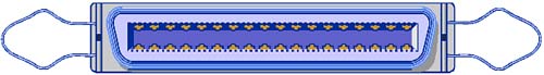
Parallel PortsThe defining characteristic of the parallel port design is implicit in its name. The port is "parallel" because it conducts its signals through eight separate wiresone for each bit of a byte of datathat are enclosed together in a single cable. The signal wires literally run in parallel from your computer to their destinationor at least they did. Better cables twist the physical wires together but keep their signals straight (and parallel). In theory, having eight wires means you can move data eight times as fast through a parallel connection than through a single wire. All else being equal, simple math would make this statement true. Although a number of practical concerns make such extrapolations impossible, throughout its life, the parallel port has been known for its speed. It beat its original competitor, the RS-232 port, hands down, outrunning the serial port's 115.2Kbps maximum by factors from two to five, even in early computers. The latest incarnations of parallel technology put the data rate through the parallel connection at over 100 times faster than the basic serial port rate. In simple installations (for example, when used for its original purpose of linking a printer to your computer), the parallel port is a model of installation elegance. Just plug in your printer, and the odds are it will work flawlesslyor that whatever flaws appear won't have anything to do with the interconnection. Despite such rave reviews, parallel ports are not trouble-free. All parallel ports are not created equal. A number of different designs have appeared during the brief history of the computer. Although new computers usually incorporate the latest, most versatile, and highest speed of these, some manufacturers skimp. Even when you buy a brand-new computer, you may end up with a simple printer port that steps back to the first generation of computer design. A suitable place to being this saga is to sort out this confusion of parallel port designs by tracing the parallel port's origins. As it turns out, the history of the parallel port is a long one, older than even the personal computer, although the name and our story begin with its introduction. HistoryNecessity isn't just the mother of invention. It also spawned the parallel port. As with most great inventions, the parallel port arose with a problem that needed to be solved. When IBM developed its first computer, its engineers looked for a simplified way to link to a printer, something without the hassles and manufacturing costs of a serial port. The simple parallel connection, already used in a similar form by some printers, was an elegant solution. Consequently, IBM's slightly modified version became standard equipment on the first computers. Because of its intended purpose, it quickly gained the "printer port" epithet. Not only were printers easy to attach to a parallel port, they were the only thing that you could connect to these first ports at the time. In truth, the contribution of computer-makers to the first parallel port was minimal. They added a new connector that better fit the space available on the computer. The actual port design was already being used on computer printers at the time. Originally created by printer-maker Centronics Data Computer Corporation and used by printers throughout the 1960s and 1970s, the connection was electrically simple, even elegant. It took little circuitry to add to a printer or computer, even in the days when designers had to use discrete components instead of custom-designed circuits. A few old-timers still cling to history and call the parallel port a Centronics port. The computer parallel port is not identical to the exact Centronics design, however. In adapting it to the computer, IBM substituted a smaller connector. The large jack used by the Centronics design had 36 pins and was too large to put where IBM wanted itsharing a card-retaining bracket with a video connector on the computer's first Monochrome Display Adapter. In addition, IBM added two new signals to give the computer more control over the printer and adjusted the timing of the signals traveling through the interface. All that said, most Centronics-style printers worked just fine with the original computer. At the time, the computer parallel port had few higher aspirations. It did its job, and did it well, moving data in one direction (from computer to printer) at rates from 50 to 150Kbps. The computer parallel port, or subtle variations of it, became ubiquitous if not universal. Any printer worth connecting to a computer used a parallel port (or so it seemed). In 1987, however, IBM's engineers pushed the parallel port in a new direction. The motive behind the change was surprisingnot a desire to improve communication but rather a band-aid solution for a temporary problem (for which it was hardly ever used). The company decided to adopt the 3.5-inch floppy disk drives for its new line of PS/2 computers at a time when all the world's computer data was mired on 5.25-inch diskettes. The new computers made no provision for building in the bigger drives. Instead, IBM believed that the entire world would instantly switch over to the new disk format. People would need to transfer their data once and only once to the new disk format. To make the transfer possible, the company released its Data Migration Facility, a fancy name for a cable and a couple disks. You used the cable to connect your old computer to your new PS/2 and software on the disks to move files through the parallel port from the old machine and disks to the new. Implicit in this design is the ability of the PS/2 parallel port to receive data as well as send it out, as to a printer. The engineers tinkered with the port design and made it work both ways, creating a bidirectional parallel port. Because of the design's intimate connection with the PS/2, it is sometimes termed the PS/2 parallel port. The Data Migration Facility proved to be an inspirational idea despite its singular shortcoming of working in only one direction. As notebook computers became popular, they also needed a convenient means to move files between machines. The makers of file transfer programs such as Brooklyn Bridge and LapLink knew a good connection when they saw it. By tinkering with parallel port signals, they discovered that they could make any parallel port operate in both directions and move data to and from computers. The key to making bidirectional transfers on the old-fashioned one-way ports was to redefine signals. They redirected tours of the signals in the parallel connector that originally had been designed to convey status information back from the printer to your computer. These signals already went in the correct direction. All that the software mavens did was to take direct control of the port and monitor the signals under their new definitions. Of course, four signals can't make a byte. They were limited to shifting four bits through the port in the backward direction. Because four bits make a nibble, the new parallel port operating mode soon earned the name nibble mode. This four-bits-at-a-time scheme had greater implications than just a new name. Half as many bits also means half the speed. Nibble mode operates at about half the normal parallel port ratestill faster than single-line serial ports but not full parallel speed. If both sides of a parallel connection had bidirectional ports, however, data transfers ran at full speed both ways. Unfortunately, as manufacturers began adapting higher-performance peripherals to use the parallel port, what once was fast performance became agonizingly slow. Although the bidirectional parallel port more than met the modest data transfer needs of printers and floppy disk drives, it lagged behind other means of connecting hard disks and networks to computers. Engineers at network adapter maker Xircom Incorporated decided to do something about parallel performance and banded together with notebook computer maker Zenith Data Systems to find a better solution. Along the way, they added Intel Corporation and formed a triumvirate called Enhanced Parallel Port Partnership. They explored two ways of increasing the data throughput of a parallel port. They streamlined the logical interface so that your computer would need less overhead to move each byte through the port. In addition, they tightly defined the timing of the signals passing through the port, minimizing wasted time and helping ensure against timing errors. They called the result of their efforts the Enhanced Parallel Port (EPP). On August 10, 1991, the organization released its first description of what it thought the next generation of parallel ports should be and do. The organization continued to work on a specification until March 1992, when it submitted Release 1.7 to the Institute of Electrical and Electronic Engineers (IEEE) to be considered as an industry standard. Although the EPP version of the parallel port could increase its performance by nearly tenfold, that wasn't enough to please everybody. The speed potential made some engineers see the old parallel port as an alternative to more complex expansion buses such as the SCSI system. With this idea in mind, Hewlett-Packard joined with Microsoft to make the parallel port into a universal expansion standard called the extended capabilities port (ECP). In November 1992, the two companies released the first version of the ECP specification, aimed at computers that use the ISA expansion bus. This first implementation added two new transfer modes to the EPP designa fast two-way communication mode between a computer and its peripherals, and another two-way mode with performance further enhanced by simple integral data compressionand defined a complete software control system. The heart of the ECP innovation was a protocol for exchanging data across a high-speed parallel connection. The devices at the two ends of each ECP transfer negotiate the speed and mode of data movement. Your computer can query any ECP device to determine its capabilities. For example, your computer can determine what language your printer speaks and set up the proper printer driver accordingly. In addition, ECP devices tell your computer the speed at which they can accept transmissions and the format of the data they understand. To ensure the quality of all transmissions, the ECP specification included error detection and device handshaking. It also allowed the use of data compression to further speed transfers. On March 30, 1994, the IEEE Standards Board approved its parallel port standard, IEEE-1284-1994. The standard included all the basic modes and parallel port designs, including both ECP and EPP. It was submitted to the American National Standards Institute and approved as a standard on September 2, 1994. The IEEE 1284 standard marked a watershed in parallel port design and nomenclature. The standard defined (or redefined) all aspects of the parallel connection, from the software interface in your computer to the control electronics in your printer. It divided the world of parallel ports in two: IEEE 1284-compatible devices, which are those that will work with the new interface, which in turn includes just about every parallel port and device ever made; and IEEE 1284-compliant devices, which are those that understand and use the new standard. This distinction is essentially between pre- and post-standardization ports. You can consider IEEE 1284-compatible ports to be "old technology" and IEEE 1284-compliant ports to be "new technology." Before IEEE 1284, parallel ports could be divided into four types: standard parallel ports, bidirectional parallel ports (also known as PS/2 parallel ports), enhanced parallel ports, and extended capabilities ports. The IEEE specification redefined the differences in ports, classifying them by the transfer mode they use. Although the terms are not exactly the same, you can consider a standard parallel port one that is able to use only nibble-mode transfers. A PS/2 or bidirectional parallel port from the old days is one that can also make use of byte-mode transfers. EPP and ECP ports are those that use EPP and ECP modes, as described by the IEEE 1284 specification. EPP and ECP remain standards separate from IEEE 1284, although they have been revised to depend on it. Both EPP and ECP rely on their respective modes as defined in the IEEE specification for their physical connections and electrical signaling. In other words, IEEE 1284 describes the physical and electrical characteristics of a variety of parallel ports. The other standards describe how the ports operate and link to your applications. ConnectorsThe best place to begin any discussion of the function and operation of the parallel port is the connector. After all, the connector is what puts the port to work. It is the physical manifestation of the parallel port, the one part of the interface and standard you can actually touch or hold in your hand. It is the only part of the interface that most people will ever have to deal with. Once you know the ins and outs of parallel connectors, you'll be able to plug in the vast majority of computer printers and the myriad of other things that now suck signals from what was once the printer's port. Unfortunately, as with the variety of operating modes, the parallel port connector itself is not a single thing. Parallel ports use three different connectors, called A, B, and C. The A connectorThe A connector appears only on computers as the output of a parallel port. Technically, it is described as a female 25-pin D-shell connector. Engineers chose this particular connector pragmaticallyit was readily available and was the smallest connector that could handle the signals required in a full parallel connection. After it became ubiquitous, the IEEE adopted it as its 1284-A connector. Figure 11.10 shows a conceptual view of the A connector. Figure 11.10. The IEEE-1284 A connector, a female 25-pin D-shell jack.
Of the 25 contacts on this parallel port connector, 17 are assigned individual signals for data transfer and control. The remaining eight serve as ground returns. Under the IEEE 1284 specification, the definition of each signal on each pin is dependent on the operating mode of the port. Only the definitions change; the physical wiring inside your computer and inside the cables does not changeif it did, shifting modes would be far from trivial. The altered definitions change the protocol, which is the signal handshaking that mediates each transfer. A single physical connector on the back of your computer can operate in any of these five modes, and the signal definitions and their operation will change accordingly. Table 11.11 lists these five modes and their signal assignments.
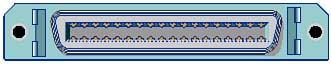
Along with standardized signal assignments, IEEE 1284 also gives us a standard nomenclature for describing the signals. In Table 11.11, as well as all following tables that refer to the standard, signal names prefaced with a lowercase n indicate that the signal goes negative when active (that is, the absence of a voltage means the signal is present). Mode changes are negotiated between your computer and the printer or other peripheral connected to the parallel port. Consequently, both ends of the connection switch modes together so that the signal assignments remain consistent at both ends of the connection. For example, if you connect an older printer that only understands compatibility mode, your computer cannot negotiate any other operating mode with the printer. It will not activate its EPP or ECP mode, so your printer will never get signals it cannot understand. This negotiation of the mode ensures backward compatibility among parallel devices. The B ConnectorThe parallel port input to printers is quite a different connector from that on your computer. In fact, the design predates personal computers, having first been used by a printer company, Centronics, which gave the connector and parallel port its alternate name (now falling into disuse). The design is a 36-pin ribbon connector (the contacts take the form of thin metal ribbons) in a D-shell. Figure 11.11 shows this connector as a jack that would appear on the back of a printer. Figure 11.11. The IEEE-1284 B connector, a 36-pin ribbon jack.
The assignment of signals to the individual pins of this connector has gone through three stages. The first standard was set by Centronics for its printers. In 1981, IBM altered this design somewhat by redefining several of the connections. Finally, in 1994, the IEEE published its standard assignments, which (like those of the A-connector) vary with operating mode. The C ConnectorGiven a chance to start over with a clean slate and no installed base, engineers would hardly come up with the confusion of two different connectors with an assortment of different, sometimes-compatible operating modes. The IEEE saw the creation of the 1284 standard as such an opportunity, one they were happy to exploit. To eliminate the confusion of two connectors and the intrinsic need for adapters to move between them, they took the logical step: They created a third connector, IEEE 1284-C. For the most part, the C connector is just the B connector with some of the air let out. Figure 11.12 shows a jack that you'd find on the back of equipment using C connectors. Figure 11.12. Conceptual view of the 1284-C parallel port connector.
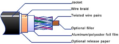
AdaptersThe standard printer cable for computers is an adapter cable. It rearranges the signals of the A connector to the scheme of the B connector. Ever since the introduction of the first computer, you needed this sort of cable just to make your printer work. Over the years they have become plentiful and cheap. To cut costs, many makers of adapter cables group all the grounds together as a single common line so that you need only 18 instead of 25 conductors in the connecting cable. Cheap adapters, which do not meet the IEEE 1284 standard, use this approach. A modern printer cable should contain a full 25 connections with the ground signals divided up among separate pins. A true IEEE 1284 printer cable is equipped with an A connector on one end and a B connector on the other, with the full complement of connections in between. As new peripherals with the 1284-C connector become available, you'll need to plug them into your computer. To attach your existing computer to a printer or other device using the C connector, you'll need an adapter cable to convert the A connector layout to the C connector design. On the other hand, if your next computer or parallel adapter uses the C connector and you plan to stick with your old printer, you'll need another variety of adapterone that translates the C connector layout to that of the B connector. CableThe high-speed modes of modern parallel ports make them finicky. When your parallel port operates in EPP or ECP mode, cable quality becomes critical, even for short runs. Signaling speed across one of these interfaces can be in the megahertz range. The frequencies far exceed the reliable limits of even short runs of the dubious low-cost printer cables. Consequently, the IEEE 1284 specification precisely details a special cable for high-speed operation. Figure 11.13 offers a conceptual view of the construction of this special parallel data cable. Figure 11.13. IEEE 1284 cable construction details.
Unlike standard parallel wiring, the data lines in IEEE 1284 cables must be double-shielded to prevent interference from affecting the signals. Each signal wire must be twisted with its ground return. Even though the various standard connectors do not provide separate pins for each of these grounds, the ground wires must be present and run the full length of the cable. The differences between old-fashioned "printer" cables and those that conform to the IEEE 1284 standard are substantial. Although you can plug in a printer with either a printer or IEEE 1284compliant cable, devices that exploit the high-speed potentials of the EPP or ECP designs may not operate properly with a noncompliant cable. Often, even when a printer fails to operate properly, the cable may be at fault. Substituting a truly IEEE 1284compliant cable will bring reluctant connections to life. Electrical OperationIn each of its five modes, the IEEE 1284 parallel port operates as if it were some kind of completely different electronic creation. When in compatibility mode, the IEEE 1284 port closely parallels the operation of the plain-vanilla printer port of bygone days. It allows data to travel in one direction only, from computer to printer. Nibble mode gives your printer (or more likely, another peripheral) a voice and allows it to talk back to your computer. In nibble mode, data can move in either of two directions, although asymmetrically. Information flows faster to your printer than it does on the return trip. Byte mode makes the journey fully symmetrical. With the shift to EPP mode, the parallel port becomes a true expansion bus. A new way of linking to your computer's bus gives it increased bidirectional speed. Many systems can run their parallel ports 10 times faster in EPP mode than in compatibility, nibble, or byte mode. ECP mode takes the final step, giving control in addition to speed. ECP can do just about anything any other expansion interface (including SCSI) can do. Because of these significant differences, the best way to get to know the parallel port is by considering each separately as if it were an interface unto itself. Our examination will follow from simple to complex, which also mirrors the history of the parallel port. Note that IEEE 1284 deals only with the signals traveling through the connections of the parallel interface. It establishes the relationship between signals and their timing. It concerns itself neither with the data that is actually transferred, with the command protocols encoded in the data, nor with the control system that produces the signals. In other words, IEEE 1284 provides an environment under which other standards such as EPP and ECP operate. That is, ECP and EPP modes are not the ECP and EPP standards, although those modes are meant to be used by the parallel ports operating under respective standards. Compatibility ModeThe least common denominator among parallel ports is the classic design that IBM introduced with its first computer. It was conceived strictly as a interface for the one-way transfer of information. Your computer sends data to your printer and expects nothing in return. After all, a printer neither stores information nor creates information on its own. In conception, this port is like a conveyor that unloads ore from a bulk freighter or rolls coal out of a mine. The raw material travels in one direction. The conveyor mindlessly pushes out stuff and more stuff, perhaps creating a dangerously precarious pile, until its operator wakes up and switches it off before the pile gets much higher than his waist. If your printer had unlimited speed or an unlimited internal buffer, such a one-way design would work. But like the coal yard, your printer has a limited capacity and may not be able to cart off data as fast as the interface shoves it out. The printer needs some way of sending a signal to your computer to warn about a potential data overflow. In electronic terms, the interface needs feedback of some kindit needs to get information from the printer that your computer can use to control the data flow. To provide the necessary feedback for controlling the data flow, the original Centronics port design and IBM's adaptation of it both included several control signals. These were designed to allow your computer to monitor how things are going with your printerwhether data is piling up, whether the printer has sufficient paper or ribbon, and even whether the printer is turned on. Your computer can use this information to moderate the outflowing gush of data or to post a message warning you that something is wrong with your printer. In addition, the original parallel port included control signals sent from your computer to the printer to tell it when the computer wanted to transfer data and to tell the printer to reset itself. The IEEE 1284 standard carries all these functions into compatibility mode. Strictly speaking, then, even this basic parallel port is not truly a one-way connection, although its feedback provisions were designed strictly for monitoring rather than data flow. For the first half of its life, the parallel port kept to this design. Until the adoption of IEEE 1284, this was the design you could expect for the port on your printer and, almost as likely, those on your computer. Each signal flowing through the parallel port in compatibility mode has its own function in handling the transfer of data. Data LinesThe eight data lines of the parallel interface convey data in all operating modes. In compatibility mode, they carry data from the host to the peripheral on connector pins 2 through 9. The higher numbered pins are the more significant to the digital code. To send data to the peripheral, the host puts a pattern of digital voltages on the data lines. Strobe LineThe presence of signals on the data lines does not, in itself, move information from host to peripheral. As your computer gets its act together, the pattern of data bits may vary in the process of loading the correct values. No hardware can ensure that all eight will always pop to the correct values simultaneously. Moreover, without further instruction your printer has no way of knowing whether the data lines represent a single character or multiple repetitions of the same character. To ensure reliable communications, the system requires a means of telling the peripheral that the pattern on the data lines represents valid information to be transferred. The strobe line does exactly that. Your computer pulses the strobe line to tell your printer that the bit-pattern on the data lines is a single valid character that the printer should read and accept. The strobe line gives its pulse only after the signals on the data lines have settled down. Most parallel ports delay the strobe signal by about half a microsecond to ensure that the data signals have settled. The strobe itself lasts for at least half a microsecond so that your printer can recognize it. (The strobe signal can last up to 500 microseconds.) The signals on the data lines must maintain a constant value during this period and slightly afterward so that your printer has a chance to read them. The strobe signal is "negative going." That is, a positive voltage (+5VDC) stays on the strobe line until your printer wants to send the actual strobe signal. Your computer then drops the positive voltage to near zero for the duration of the strobe pulse. The IEEE 1284 specification calls this signal nStrobe. Busy LineSending data to your printer is a continuous cycle of setting up the data lines, sending the strobe signal, and putting new values on the data lines. The parallel port design typically requires about two microseconds for each turn of this cycle, allowing a perfect parallel port to dump out nearly half a million characters a second into your hapless printer. (As you will see, the actual maximum throughput of a parallel port is much lower than this.) For some printers, coping with that data rate is about as daunting as trying to catch machine gun fire with your bare hands. Before your printer can accept a second character, its circuitry must do something with the one it has just received. Typically, the printer will need to move the character into its internal buffer. Although the character moves at electronic speeds, it does not travel instantaneously. Your printer needs to be able to tell your computer to wait for the processing of the current character before sending the next. The parallel port's busy line gives your printer the needed breathing room. Your printer switches on the busy signal as soon as it detects the strobe signal and keeps the signal active until it is ready to accept the next character. The busy signal can last for a fraction of a second (even as short as a microsecond), or your printer could hold it on indefinitely while it waits for you to correct some error. No matter how long the busy signal is on, it keeps your computer from sending out more data through the parallel port. It functions as the basic flow-control system. Acknowledge LineThe final part of the flow-control system of the parallel port is the acknowledge line. It tells your computer that everything has gone well with the printing of a character or its transfer to the internal buffer. In effect, it is the opposite of the busy signal, telling your computer that the printer is ready rather than unready. Whereas the busy line says, "Whoa," the acknowledge line says, "Giddyap!" The acknowledge signal is the opposite of the busy signal in another way: It is negative going whereas the busy signal is positive going. The IEEE 1284 specification calls this signal nAck. When your printer sends out the acknowledge signal, it completes the cycle of sending a character. Typically the acknowledge signal on a conventional parallel port lasts about eight microseconds, stretching a single character cycle across the port to 10 microseconds. (IEEE 1284 specifies the length of nAck to be between 0.5 and 10 microseconds.) If you assume the typical length of this signal for a conventional parallel port, the maximum speed of the port works out to about 100,000 characters per second. SelectIn addition to transferring data to the printer, the basic parallel port allows your printer to send signals back to your computer so that your computer can monitor the operation of the printer. The original IBM design of the parallel interface includes three such signals that tell your computer when your printer is ready, willing, and able to do its job. In effect, these signals give your computer the ability to remotely sense the condition of your printer. The most essential of these signals is select. The presence of this signal on the parallel interface tells your computer that your printer is online (that is, the printer is switched on and is in its online mode, ready to receive data from your computer). In effect, it is a remote indicator for the online light on your printer's control panel. If this signal is not present, your computer assumes that nothing is connected to your parallel port and doesn't bother with the rest of its signal repertory. Because the rest state of a parallel port line is an absence of voltage (which would be the case if nothing were connected to the port to supply the voltage), the select signal takes the form of a positive signal (nominally +5VDC) that in compatibility mode under the IEEE 1284 specification stays active the entire period your printer is online. Paper EmptyTo print anything your printer needs paper, and the most common problem that prevents your printer from doing its job is running out of paper. The paper empty signal warns your computer when your printer runs out. The IEEE 1284 specification calls this signal PError for paper error, although it serves exactly the same function. Paper empty is an information signal. It is not required for flow control because the busy signal more than suffices for that purpose. Most printers will assert their busy signals for the duration of the period they are without paper. Paper empty tells your computer the specific reason that your printer has stopped data flow. This signal allows your operating system or application to flash a message on your monitor to warn you to load more paper. FaultThe third printer-to-computer status signal is fault, a catchall for warning of any other problems that your printer may developout of ink, paper jams, overheating, conflagrations, and other disasters. In operation, fault is actually a steady-state positive signal. It dips low (or off) to indicate a problem. At the same time, your printer may issue its other signals to halt the data flow, including busy and select. It never hurts to be extra sure. Because this signal is "negative going," the IEEE specification calls it nFault. Initialize PrinterIn addition to the three signals your printer uses to warn of its condition, the basic parallel port provides three control signals that your computer can use to command your printer without adding anything to the data stream. Each of these three provides its own hard-wired connection for a specific purpose. These include one to initialize the printer, another to switch it to online condition (if the printer allows a remote control status change), and a final signal to tell the printer to feed the paper up one line. The initialize printer signal helps your computer and printer keep in sync. Your printer can send a raft of different commands to your printer to change its mode of operation, change font, alter printing pitch, and so on. Each of your applications that share your printer might send out its own favored set of commands. And many applications are like sloppy in-laws that come for a visit and fail to clean up after themselves. The programs may leave your printer in some strange condition, such as set to print underscored boldface characters in agate size type with a script typeface. The next program you run might assume some other condition and blithely print out a paycheck in illegible characters. Initialize printer tells your printer to step back to ground zero. Just as your computer boots up fresh and predictably, so does your printer. When your computer sends your printer the initialize printer command, it tells the printer to boot up (that is, reset itself and load its default operating parameters with its startup configuration of fonts, pitches, typefaces, and the like). The command has the same effect as you switching off the printer and turning it back on and simply substitutes for adding a remote control arm on your computer to duplicate your actions. During normal operation, your computer puts a constant voltage on the initialize printer line. Removing the voltage tells your printer to reset. The IEEE 1284 specification calls this negative-going signal nInit. Select InputThe signal that allows your computer to switch your printer online and offline is called select input. The IEEE 1284 specification calls it nSelectIn. It is active, forcing your printer online, when it is low or off. Switching it to high deselects your printer. Not all printers obey this command. Some have no provisions for switching themselves on- and offline. Others have setup functions (such as a DIP switch) that allow you to defeat the action of this signal. Auto Feed XTAt the time IBM imposed its print system design on the rest of the world, different printers interpreted the lowly carriage return in one of two ways. Some printers took it literally. Carriage return means to move the printhead carriage back to its starting position on the left side of the platen. Other printers thought more like typewriters. Moving the printhead full left also indicated the start of a new line, so they obediently advanced the paper one line when they got a carriage return command. IBM, being a premiere typewriter-maker at the time, opted for this second definition. To give printer developers flexibility, however, the IBM parallel port design included the Auto Feed XT signal to give your computer command of the printer's handling of carriage returns. Under the IEEE 1284 specification, this signal is called nAutoFd. By holding this signal low or off, your computer commands your printer to act in the IBM and typewriter manner, adding a line feed to every carriage return. Making this signal high tells your printer to interpret carriage returns literally and only move the printhead. Despite the availability of this signal, most early computer printers ignored it and did whatever their setup configuration told them to do with carriage returns. Nibble ModeEarly parallel ports used unidirectional circuitry for their data lines. No one foresaw the need for your computer to acquire data from your printer, so there was no need to add the expense or complication of bidirectional buffers to the simple parallel port. This tradition of single-direction design and operation continues to this day in the least expensive (which, of course, also means cheapest) parallel ports. Every parallel port does, however, have five signals that are meant to travel from the printer to your computer. These include (as designated by the IEEE 1284 specification) nAck, Busy, PError, Select, and nFault. If you could suspend the normal operation of these signals temporarily, you could use four of them to carry data back from the printer to your computer. Of course, the information would flow at half speed, four bits at a time. This means of moving data is the basis of nibble mode, so called because the computer community calls half a byte (the aforementioned four bits) a nibble. Using nibble mode, any parallel port can operate bidirectionally full speed forward but half speed in reverse. Nibble mode requires that your computer take explicit command and control the operation of your parallel port. The port itself merely monitors all its data and monitoring signals and then relays the data to your computer. Your computer determines whether to regard your printer's status signals as backward-moving data. Of course, this system also requires that the device at the other end of the parallel port (your printer or whatever) know that it has switched into nibble mode and understand what signals to put where and when. The IEEE 1284 specification defines a protocol for switching into nibble mode and how computer and peripherals handle the nibble-mode signals. The process is complex, involving several steps. First, your computer must identify whether the peripheral connected to it recognizes the IEEE standard. If not, all bets are off for using the standard. Products created before IEEE 1284 was adopted needed special drivers that matched the port to a specific peripheral. Because the two were already matched, they knew everything they needed to know about each other without negotiation. The pair could work without understanding the negotiation process or even the IEEE 1284 specification. Using the specification, however, allows your computer and peripherals to do the matching without your intervention. Once your computer and peripheral decide they can use nibble mode, your computer signals to the peripheral to switch to the mode. Before the IEEE 1284 standard, the protocol was proprietary to the parallel port peripheral. The standard gives all devices a common means of controlling the switchover. After both your computer and parallel port peripheral have switched to nibble mode, the signals on the interface get new definitions. In addition, nibble mode itself operates in two modes or phases, and the signals on the various parallel port lines behave differently in each mode. These modes include reverse idle phase and reverse data transfer phase. In reverse idle phase, the PtrClk signal (nAck in compatibility mode) operates as an attention signal from the parallel port peripheral. Activating this signal tells the parallel port to issue an interrupt inside your computer, signaling that the peripheral has data available to be transferred. Your computer acknowledges the need for data and requests its transfer by switching the HostBusy signal (nAutoFd in compatibility mode) to low or off. This switches the system to reverse data transfer phase. Your computer switches the HostBusy signal to high again after the completion of the transfer of a full data byte. When the peripheral has mode data ready and your computer switches HostBusy back to low again, another transfer begins. If it switches to low without the peripheral having data available to send, the transition reengages reverse idle phase. Because moving a byte from peripheral to computer requires two nibble transfers, each of which requires the same time as one byte transfer from computer to peripheral, reverse transfers in nibble mode operate at half speed at best. The only advantage of nibble mode is its universal compatibility. Even before the IEEE 1284 specification, it allowed any parallel port to operate bidirectionally. Because of this speed penalty alone, if you have a peripheral and parallel port that lets you choose the operating mode for bidirectional transfers, nibble mode is your least attractive choice. Byte ModeUnlike nibble mode, byte mode requires special hardware. The basic design for byte-mode circuitry was laid down when IBM developed its PS/2 line of computers and developed the Data Migration Facility. By incorporating bidirectional buffers in all eight of the data lines of the parallel port, IBM enabled them to both send and receive information on each end of the connection. Other than that change, the new design involved no other modifications to signals, connector pin assignments, or the overall operation of the port. Before the advent of the IEEE standard, these ports were known as PS/2 parallel ports or bidirectional parallel ports. IEEE 1284 does more than put an official industry imprimatur on the IBM design, however. The standard redefines the bidirectional signals and adds a universal protocol for negotiating bidirectional transfers. As with nibble mode, a peripheral in byte mode uses the PtrClk signal to trigger an interrupt in the host computer to advise that the peripheral has data available for transfer. When the computer services the interrupt, it checks the port nDataAvail signal, a negative-going signal that indicates a byte is available for transfer when it goes low. The computer can then pulse off the HostBusy signal to trigger the transfer using the HostClk (nStrobe) signal to read the data. The computer raises the HostBusy signal again to indicate the successful transfer of the data byte. The cycle can then repeat for as many bytes as need to be sent. Because byte mode is fully symmetrical, transfers occur at the same speed in either direction. The speed limit is set by the performance of the port hardware, the speed at which the host computer handles the port overhead, and the length of timing cycles set in the IEEE 1284 specification. Potentially the design could require as little as four micro seconds for each byte transferred, but real-world systems peak at about the same rate as conventional parallel ports (100,000 bytes per second). Enhanced Parallel Port ModeWhen it was introduced, the chief innovation of the Enhanced Parallel Port (EPP) was its improved performance, thanks to a design that hastened the speed at which your computer could pack data into the port. The EPP design altered port hardware so that instead of using byte-wide registers to send data through the port, your computer could dump a full 32-bit word of data directly from its bus into the port. The port would then handle all the conversion necessary to repackage the data into four-byte-wide transfers. The reduction in computer overhead and more efficient hardware design enabled a performance improvement by a factor of 10 in practical systems. This speed increase required more stringent specifications for printer cables. The IEEE 1284 specification does not get into the nitty-gritty of linking the parallel port circuitry to your computer, so it does not guarantee that a port in EPP mode will deliver all this speed boost. Moreover, the IEEE 1284 cable specs are not as demanding as the earlier EPP specs. EPP mode of the IEEE 1284 specification uses only six signals in addition to the eight data lines for controlling data transfers. Three more connections in the interface are reserved for use by individual manufacturers and are not defined under the standard. A given cycle across the EPP mode interface performs one of four operations: writing an address, reading an address, writing data, or reading data. The address corresponds to a register on the peripheral. The data operations are targeted on that address. Multiple data bytes may follow a single address signal as a form of burst mode. nWriteData can travel both ways through an EPP connection. The nWrite signal tells whether the contents of the data lines are being sent from your computer to a peripheral or from a peripheral to your computer. When the nWrite signal is set to low, it indicates data is bound for the peripheral. When set to high, it indicates data sent from the peripheral. nDStrobeSoundboards are heavy feeders when it comes to system resources. A single soundboard may require multiple interrupts, a wide range of input/output ports, and a dedicated address range in High DOS memory. Because of these extensive resource demands, the need for numerous drivers, and often-poor documentation, soundboards are the most frustrating expansion products to add to a computer. In fact, a soundboard may be the perfect gift to surreptitiously gain revenge, letting you bury the hatchet with an estranged friend without the friend knowing you've sliced solidly into his back. As with other parallel port transfers, your system needs a signal to indicate when the bits on the data lines are valid and accurate. EPP mode uses a negative-going signal called nDStrobe for this function in making data operations. Although this signal serves the same function as the strobe signal on a standard parallel port, it has been moved to a different pin, that used by the nAutoFd signal in compatibility mode. nAStrobeTo identify a valid address on the interface bus, the EPP system uses the nAStrobe signal. This signal uses the same connection as nSelectIn during compatibility mode. nWaitTo acknowledge that a peripheral has properly received a transfer, it deactivates the negative-going nWait signal (making it a positive voltage on the bus). By holding the signal positive, the peripheral signals the host computer to wait. Making the signal negative indicates that the peripheral is ready for another transfer. IntrA peripheral connected to the EPP interface can signal to the host computer that it requires immediate service by sending out the Intr signal. The transition between low and high states of this signal indicates a request for an interrupt (that is, the signal is "edge triggered"). EPP mode does not allocate a signal to acknowledge that the interrupt request was received. nInitThe escape hatch for EPP mode is the nInit signal. When this signal is activated (making it low), it forces the system out of EPP mode and back into compatibility mode. Extended Capabilities Port ModeWhen operating in ECP mode, the IEEE 1284 port uses seven signals to control the flow of data through the standard eight data lines. ECP mode defines two data-transfer signaling protocolsone for forward transfers (from computer to peripheral) and one for reverse transfers (peripheral to computer)and the transitions between them. Transfers are moderated by closed-loop handshaking, which guarantees that all bytes get where they are meant to go, even if the connection is temporarily disrupted. Because all parallel ports start in compatibility mode, your computer and its peripherals must first negotiate with one another to arrange to shift into ECP mode. Your computer and its software initiate the negotiation (as well as manage all aspects of the data transfers). Following a successful negotiation to enter into ECP mode, the connection enters its forward idle phase. HostClkTo transfer information or commands across the interface, your computer starts from the forward idle phase and puts the appropriate signals on the data line. To signal to your printer or other peripheral that the values on the data lines are valid and should be transferred, your computer activates its HostClk signal, setting it to a logical high. PeriphAckThe actual transfer does not take place until your printer or other peripheral acknowledges the HostClk signal by sending back the PeriphAck signal, setting it to a logical high. In response, your computer switches the HostClk signal to low. Your printer or peripheral then knows it should read the signals on the data lines. Once it finishes reading the data signals, the peripheral switches the PeriphAck signal to low. This completes the data transfer. Both HostClk and PeriphAck are back to their forward idle phase norms, ready for another transfer. nPeriphRequestWhen a peripheral needs to transfer information back to the host computer or to another peripheral, it makes a request by driving the nPeriphRequest signal low. The request is a suggestion rather than a command because only the host computer can initiate or reverse the flow of data. The nPeriphRequest signal typically causes an interrupt in the host computer to make this request known. nReverseRequestTo allow a peripheral to send data back to the host or to another device connected to the interface, the host computer activates the nReverseRequest signal by driving it low, essentially switching off the voltage that otherwise appears there. This signals to the peripheral that the host computer will allow the transfer. nAckReverseTo acknowledge that it has received the nReverseRequest signal and that it is ready for a reverse-direction transfer, the peripheral asserts its nAckReverse signal, driving it low. The peripheral can then send information and commands through the eight data lines and the PeriphAck signal. PeriphClkTo begin a reverse transfer from peripheral to computer, the peripheral first loads the appropriate bits onto the data lines. It then signals to the host computer that it has data ready to transfer by driving the PeriphClk signal low. HostAckYour computer responds to the PeriphClk signal by switching the HostAck signal from its idle logical low to a logical high. The peripheral responds by driving PeriphClk high. When the host accepts the data, it responds by driving the HostAck signal low. This completes the transfer and returns the interface to the reverse idle phase. Data LinesAlthough the parallel interface uses the same eight data lines to transfer information as do other IEEE 1284 port modes, it supplements them with an additional signal to indicate whether the data lines contain data or a command. The signal used to make this nine-bit information system changes with the direction of information transfer. When ECP mode transfers data from the computer host to a peripheral (that is, during a forward transfer), it uses the HostAck signal to specify a command or data. When a peripheral originates the data being transferred (a reverse transfer), it uses the PeriphAck signal to specify a command or data. Logical InterfaceYour computer controls each of its parallel ports through a set of three consecutive input/output ports. The typical computer sets aside three sets of these ports for three parallel ports, although most systems provide the matching hardware only for one. The base addresses used by parallel ports include 03BC(hex), 0378(hex), and 0278(hex). When Windows boots up, it scans these addresses and assigns a logical name to each. These names are LPT1, LPT2, and LPT3. The name is a contraction of Line Printer, echoing the original purpose of the port. The port with the name LPT1 can also use the alias PRN. You can use these names at the system command prompt to identify a parallel port and the printer connected to it. The computer printer port was designed to be controlled by a software driver. Your computer's BIOS provides a rudimentary driver, but most advanced operating systems similarly take direct hardware control of the parallel port through their own software drivers. Windows includes a parallel port driver of its own. You may need to install drivers for any device that connects to your parallel port. For example, every printer requires it own driver (many of whichbut not allare built in to Windows). ControlEven in its immense wisdom, a microprocessor can't fathom how to operate a parallel port by itself. It needs someone to tell it how to move the signals around. Moreover, the minutiae of constantly taking care of the details of controlling a port would be a waste of the microprocessor's valuable time. Consequently, system designers created help systems for your computer's big brain. Driver software tells the microprocessor how to control the port, and port hardware handles all the details of port operation. As parallel ports have evolved, so have these aspects of their control. The software that controls the traditional parallel port that's built in to the firmware of your computer has given way to a complex system of drivers. The port hardware, too, has changed to both simplify operation and to speed it up. These changes don't follow the neat system of modes laid down by IEEE 1284. Instead, they have undergone a period of evolution in reaching their current condition. Traditional Parallel PortsIn the original computer, each of its parallel ports linked to the computer's microprocessor through three separate I/O ports, each controlling its own register. The address of the first of these registers served as the base address of the parallel port. The other two addresses are next higher in sequence. For example, when the first parallel port in a computer has a base address of 0378 (hex), the other two I/O ports assigned it have addresses of 0379 (hex) and 037A (hex). The register at the base address of the parallel port serves as a data latch, called the printer data register, which temporarily holds the values passed along to it by your computer's microprocessor. Each of the eight bits of this port is tied to one of the data lines leading out of the parallel port connector. The correspondence is exact. For example, the most significant bit of the register connects to the most significant bit on the port connector. When your computer's microprocessor writes values to the base register of the port, the register latches those values until your microprocessor sends newer values to the port. Your computer uses the next register on the parallel port, corresponding to the next I/O port, to monitor what the printer is doing. Termed the printer status register, the various bits that your microprocessor can read at this I/O port carry messages from the printer back to your computer. The five most significant bits of this register directly correspond to five signals appearing in the parallel cable: Bit 7 indicates the condition of the busy signal; bit 6, acknowledge; bit 5, paper empty; bit 4, select; and bit 3, error. The remaining three bits of this register (bits 2, 1, and 0the least significant bits) served no function in the original computer parallel port. To send commands to your printer, your computer uses the third I/O port, offset two ports from the base address of the parallel port. The register there, called the printer control register, relays commands through its five least significant bits. Of these, four directly control corresponding parallel port lines. Bit 0 commands the strobe line; bit 1, the Auto Feed XT line; bit 2, the initialize line; and bit 3, the select line. To enable your printer to send interrupts to command the microprocessor's attention, your computer uses bit 4 of the printer control register. Setting this bit to high causes the acknowledge signal from the printer to trigger a printer interrupt. During normal operation your printer, after it receives and processes a character, changes the acknowledge signal from a logical high to a low. Set bit 4, and your system detects the change in the acknowledge line through the printer status register and executes the hardware interrupt assigned to the port. In the normal course of things, this interrupt simply instructs the microprocessor to send another character to the printer. All the values sent to the printer data register and the printer control register are put in place by your computer's microprocessor, and the chip must read and react to all the values packed into the printer status register. The printer gets its instructions for what to do from firmware that is part of your system's ROM BIOS. The routines coded for interrupt vector 017 (hex) carry out most of these functions. In the normal course of things, your applications call interrupt 017 (hex) after loading appropriate values into your microprocessor's registers, and the microprocessor relays the values to your printer. These operations are very microprocessor intensive. They can occupy a substantial fraction of the power of a microprocessor (particularly that of older, slower chips) during print operations. Enhanced Parallel PortsIntel set the pattern for Enhanced Parallel Port (EPP) by integrating the design into the 386SL chipset (which comprised a microprocessor and a support chip, the 386SL itself, and the 82360SL I/O subsystem chip, which together required only memory to make a complete computer). The EPP was conceived as a superset of the standard and PS/2 parallel ports. As with those designs, compatible transfers require the use of the three parallel port registers at consecutive I/O port addresses. However, EPP adds five new registers to the basic three. Although designers are free to locate these registers wherever they want because they are accessed using drivers, in the typical implementation, these registers occupy the next five I/O port addresses in sequence. EPP Address RegisterThe first new register (offset three from the base I/O port address) is called the EPP address register. It provides a direct channel through which your computer can specify addresses of devices linked through the EPP connection. By loading an address value in this register, your computer could select from among multiple devices attached to a single parallel port, at least once parallel devices using EPP addressing become available. EPP Data RegistersThe upper four ports of the EPP system interface (starting at offset four from the base port) link to the EPP data registers, which provide a 32-bit channel for sending data to the EPP data buffer. The EPP port circuitry takes the data from the buffer, breaks it into four separate bytes, and then sends the bytes through the EPP data lines in sequence. Substituting four I/O ports for the one used by standard parallel ports moves the conversion into the port hardware, relieving your system from the responsibility of formatting the data. In addition, your computer can write to the four EPP data registers simultaneously using a single 32-bit double-word in a single clock cycle in computers that have 32-bit data buses. In lesser machines, the EPP specification also allows for byte-wide and word-wide (16-bit) write operations through to the EPP data registers. Unlike standard parallel ports, which require your computer's microprocessor to shepherd data through the port, the Enhanced Parallel Port works automatically. It requires no other signals from your microprocessor after it loads the data in order to carry out a data transfer. The EPP circuitry itself generates the data strobe signal on the bus almost as soon as your microprocessor writes to the EPP data registers. When your microprocessor reads data from the EPP data registers, the port circuitry automatically triggers the data strobe signal to tell whatever device that's sending data to the EPP connection that your computer is ready to receive more data. The EPP port can consequently push data through to the data lines with a minimum of transfer overhead. This streamlined design is one of the major factors that enables the EPP to operate so much faster than standard ports. Fast Parallel Port Control RegisterTo switch from standard parallel port to bidirectional to EPP operation requires only plugging values into one of the registers. Although the manufacturers can use any design they want, needing only to alter their drivers to match, most follow the pattern set in the SL chips. Intel added a software-controllable fast parallel port control register as part of the chipset. This corresponds to the unused bits of the standard parallel port printer control register. Setting the most significant bit (bit 7) of the fast parallel port control register to high engages EPP operation. Setting this bit to low (the default) forces the port into standard mode. Another bit controls bidirectional operation. Setting bit 6 of the fast parallel port control register to high engages bidirectional operation. When low, bit 6 keeps the port unidirectional. In most computers, an EPP doesn't automatically spring to life. Simply plugging your printer into EPP hardware won't guarantee fast transfers. Enabling the EPP requires a software driver that provides the link between your software and the EPP hardware. Extended Capabilities PortsAs with other variations on the basic parallel port design, your computer controls an Extended Capabilities Port (ECP) through a set of registers. To maintain backward compatibility with products requiring access to a standard parallel port, the ECP design starts with the same trio of basic registers. However, it redefines the parallel port data in each of the port's different operating modes. The ECP design supplements the basic trio of parallel port registers with an additional set of registers offset at port addresses 0400 (hex) higher than the base registers. One of these, the extended control register, controls the operating mode of the ECP port. As with other improved parallel port designs, ECP behaves exactly like a standard parallel port in its default mode. Your programs can write bytes to its data register (located at the port's base address, just as with a standard parallel port) to send the bits through the data lines of the parallel connection. Switch to EPP or ECP mode, and your programs can write at high speed to a register as wide as 32 bits. The ECP design allows for transfers 8, 16, or 32 bits wide at the option of the hardware designer. To allow multiple devices to share a single parallel connection, the ECP design incorporates its own addressing scheme that allows your computer to separately identify and send data to up to 128 devices. When your computer wants to route a packet or data stream through the parallel connection to a particular peripheral, it sends out a channel address command through the parallel port. The command includes a device address. When an ECP parallel device receives the command, it compares the address to its own assigned address. If the two do not match, the device ignores the data traveling through the parallel connection until your computer sends the next channel address command through the port. When your computer fails to indicate a channel address, the data gets broadcast to all devices linked to the parallel connection. |
| [ Team LiB ] |
|